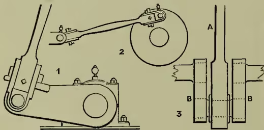
Crank, in Machinery, is a lever or arm on a shaft, driven by hand (e.g. a winch-handle), or by a connecting-rod, its object being to convert reciprocating motion into rotary motion. Engine-crank which convert the to and fro motion of the piston into continuous rotation of crank-shaft are connected to the piston-rod end by the connecting-rod. They are, when single, of steel, wrought-iron, or cast-iron, the crank in this case being either a simple arm, enlarged at one end to fit over the shaft, and with a pin at the other end embraced by the rod end (fig. 1); or else a disc centred on the shaft, with crank-pin as before (fig. 2). This last form is well balanced. When double, as is usual in large engines (fig. 3), they are now often built up of steel, the two arms being shrunk on to the shaft, and pin on to them. In two positions during each turn, a connecting-rod exerts no power of rotation. These are when rod A and crank-arms B are parallel (as in fig. 3 and opposite position), and are the dead centres; all the push or pull of the rod only causes pressure on shaft-bearings. To carry the crank over these points either a heavy wheel (fly-wheel) is attached to the shaft, which stores up energy during other parts of the revolution, and gives it out at these points, or else two or more cranks are so placed on the shaft that when one is on its dead centre, the others are exerting nearly their maximum effort, which is when rod and crank are at right angles. See TREAD-WHEEL.