Dynamo-electric Machines are machines for generating electric currents by means of the relative movement of conductors and magnets. Faraday discovered in 1831 that an electric current is induced in a conductor when it is moved across the pole of a magnet, so that it cuts the lines of magnetic force, or (more generally) whenever the number of these lines which passes through the circuit of the conductor is in any way varied. If, for example, a coil of wire, the ends of which are connected so that the whole forms a closed circuit, be suddenly withdrawn from the pole of a magnet, a transient electric current is induced in it, while the lines of magnetic force which proceed from the pole are ceasing to be present within the coil. If the coil be replaced, a current will again be induced, but in the contrary direction. Similarly, a transient current is induced if the coil be held at rest while the magnet is drawn away; or, again, if the coil be turned round so that the direction of the lines of force through it becomes reversed, in which case the effect will be twice as great as before. Any movement which causes an alteration to take place in the amount of magnetic induction through the coil produces a transient current, the electromotive force of which is proportional to the rate at which this alteration takes place. The whole amount of electricity produced is the same whether the movement be fast or slow. When the movement is slow, the current lasts longer in proportion as its strength is less. To produce the movement requires an exertion of mechanical work, which finds its equivalent in the energy of the induced current.
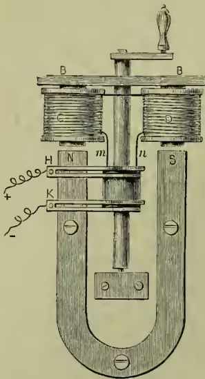
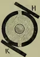
Faraday's discovery was immediately followed by the invention of numerous forms of magneto-electric machines, as they were then called, in most of which a steel horseshoe magnet was made to rotate over a pair of coils wound on a fixed armature, or the armature and coils were made to rotate while the magnet was held fixed. Fig. 1 is an example of one of these early forms, in which the armature, BB, with the bobbins, C, D, which consist of coils wound upon iron cores fixed to the armature, revolves in front of the magnet poles, N, S. In every half-revolution the lines of magnetic force through the bobbins have their direction reversed, and a series of transient currents are consequently produced in the coils. These pass to the external part of the circuit through the spring brushes, H, K, which make contact with a revolving collector, consisting of insulated metallic rings on the axle, to which the ends, m, n, of the coils are attached. If m were always in contact with H, and n with K, it is obvious that each successive transient current would take the direction opposite to its predecessor—the direction of the current would alternate at every half-revolution. On the other hand, it is easy, by splitting the rings, to arrange the collector so that H is in contact with m for half a revolution, and then with n for the other half, while K is in contact first with n, and then with m, with the effect that the successive currents all have the same direction in the external portion of the circuit. The collector is then called a commutator. A common form of commutator is shown in fig. 2.
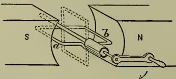
An ideally simple form of dynamo is represented diagrammatically in fig. 3, which represents a conductor consisting of a single loop of wire revolving in the magnetic field between the poles of a magnet, NS, so that at every half-revolution the lines of force have their direction of passing through the loop reversed, and a series of transient currents is consequently induced in the loop. Here, again, a commutator is required if the currents are to have one continuous direction in the external portion of the circuit. In the position sketched (by full lines), the side, a, of the rectangular loop is cutting the lines of force in one direction, and the side, b, is cutting them in the other, and both these movements are contributing to produce electromotive force in one direction round the loop; the other two sides (i.e. the front and the back) of the loop do not cut lines of force, and therefore do not contribute to the production of electromotive force. As the loop approaches the vertical position (shown by dotted lines), the component motion of the sides across the lines of magnetic force becomes reduced, and the electromotive force diminishes, till, at the vertical position, it disappears entirely, for there the sides of the loop are moving (at the instant) along the lines of force. After that they begin to cut the lines of force again, but in the reverse direction, and an electromotive force opposite to the last begins to act, which reaches its maximum when the coil is again horizontal. The same variations are repeated as the coil turns through the remaining half of its revolution. The strength of the current follows similar fluctuations, being determined by the electromotive force and by the resistance of the circuit, including the resistance of the revolving loop itself.
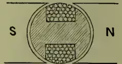
The effect of the revolving conductor in producing electromotive force may be increased (1) by increasing the speed of rotation; (2) by forming the loop with more than one turn of wire so as to make a coil, the whole effect is then the sum of the effects due to the individual turns; (3) by strengthening the magnetic field. One very important method of doing this is to furnish the revolving coil with an iron core, the effect of which is to increase the magnetic induction through the loop, across the space from pole to pole, by providing an easier path for the lines of magnetic force to cross this gap. In early dynamos the armature (as the revolving-piece is called) frequently consisted of a coil of many turns wound on an iron core, in the manner illustrated by fig. 4, which shows in section the simple shuttle-wound armature introduced by Siemens in 1856. The ends of the coil were brought to a commutator like that of fig. 2, and the effect was to produce currents which were uniform in direction. They were, however, very far from uniform in strength, varying from zero to a maximum twice in every revolution of the shaft.
In the early dynamos permanent steel magnets were used to produce the field in which the armature moved, but it was soon recognised that electro-magnets might be employed instead, and in 1863 Mr Wilde introduced a machine with large electro-magnets, which were excited by a small auxiliary armature revolving between the poles of a permanent magnet. Before this it had been proposed in machines with permanent magnets to supplement the magnetism when the machine was in action, by having coils wound upon the magnets, and by allowing the current produced in the machine itself to pass through these coils. It was not till 1867, however, that it became known that steel magnets were wholly unnecessary, and that dynamos with electro-magnets might be made entirely self-exciting. Even when the cores of the electro-magnets are of soft iron, there is enough residual magnetism to initiate a feeble current; this develops more magnetism, which in its turn develops more current, and so the process goes on until full magnetisation is reached. The principle of self-excitation was enunciated independently, and almost simultaneously, by Wheatstone, Werner Siemens, and S. A. Varley; it is now made use of in all except the smallest machines. The term 'dynamo-electric' was at first applied to distinguish those machines which were self-exciting from 'magneto-electric' machines, which had permanent magnets to give the field; but this distinction is no longer maintained, and the name 'dynamo' is now used in the wider sense defined above.
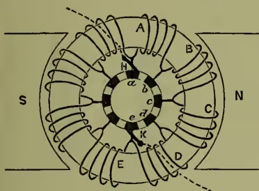
An extremely important step in the development of the dynamo was taken in 1870 by Gramme, who introduced a form of armature which, for the first time, gave a current not merely continuous in direction, but also sensibly uniform in strength. The Gramme ring armature is shown diagrammatically in fig. 5. It consists of a ring-shaped iron core, revolving in the magnetic field, and having a series of coils, A, B, C, &c., wound upon it. These are joined to one another in a continuous series, and also to the insulated segments of a commutator, a, b, c, which revolves with the ring, and from which the current is taken by brushes, H, K. Consider now the action of the field in producing electromotive force in any one of the coils, such as A. Near the place in which it is sketched, the coil A is moving in a direction parallel, or nearly parallel, to the lines of force, and, therefore, is having little or no electromotive force induced in it. But by the time the ring has made half a revolution, the same coil will have the lines of force within it reversed. Between these two positions, therefore, there must have been a generation of electromotive force, and this will in fact be going on most actively half-way between the two places. The coil C is at present the most active contributor of electromotive force, but B and D, the coils lying in front of and behind it, are also contributing a share, and the whole electromotive force between A and E, so far as that side of the ring is concerned, will be the sum of the several effects due to all the coils from A to E. A little consideration will show that the same action is going on on the other side of the ring, so that if the brushes be applied at a and e they will take off to the external portion of the circuit a current, half of which is contributed by one side, and half by the other side of the ring, the two sides acting like two groups of battery cells arranged in parallel and of equal resistance and equal electromotive force. The whole electromotive force in the armature is the same as that produced by the coils on one side alone, but the internal resistance is halved by the division of the current between the two sides. In actual Gramme armatures, the number of coils on the ring is very much greater than the number shown in the sketch, and each brush is made wide enough where it presses on the commutator to touch two of the segments at once. Hence the current is never interrupted, and the fluctuations in its strength, which occur as one segment passes out of contact and another comes in, may be made almost indefinitely small. As each coil passes, it is for the instant short-circuited through the brush, and this would give rise to a waste of energy in the coil and to sparking at the brushes, were it not that the brushes are set to bear on the commutator at the points where the development of electromotive force in the corresponding pair of coils is a minimum. These neutral points, as they are called, are not exactly midway between S and N, but are in advance of that position in consequence of the magnetic field within the ring being distorted through the action of the currents in the armature coils. Hence the brushes require to have what is called 'lead,' and this lead has in general to be adjusted whenever the output of the machine is considerably varied, more lead being needed if it happen that the arma- ture current is increased while the field magnets remain of constant, or nearly constant, strength. The adjustment of the brushes is a matter of much practical importance in the management of a dynamo, for the sparking to which faulty adjustment gives rise speedily wears away the commutator bars as well as the brushes themselves.
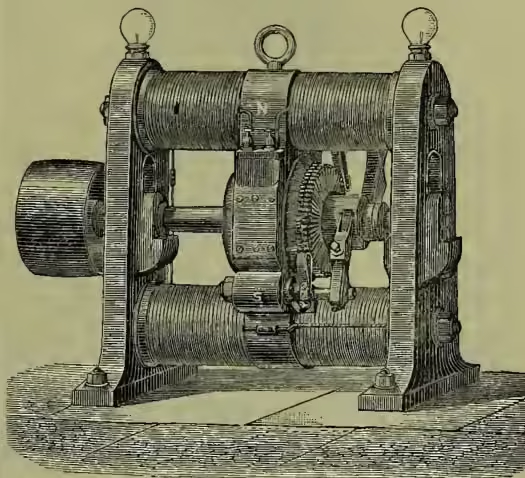
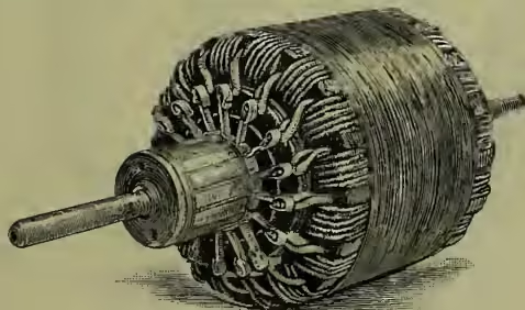
A small practical Gramme dynamo of an early form is shown in fig. 6. In this example two field magnets conspire to produce a north pole at N, and other two to produce a south pole at S. The commutator is a series of copper bars mounted on an insulating hub fixed to the shaft, and separated from one another by thin stripes of mica or other insulating material; these bars have radial projections, which are soldered to the junctions of successive armature coils. Each brush consists of a flat bundle of copper wires pressed lightly against the commutator by a spring. The core of the armature is a ring made up of many turns of soft iron wire, on which insulated copper wire is wound to form the coils. It is essential that the core of the armature should not be solid, for in that case currents would be developed in the substance of the moving iron itself to such an extent as very seriously to impair the efficiency of the machine. Hence the core of dynamo armatures is always subdivided, by being made up either of wire, or more usually of thin plates more or less carefully insulated from one another. Fig. 7 shows the armature of a small Gramme dynamo, removed from its place between the pole-pieces.
Two years after the introduction of the ring armature by Gramme, it was shown by Von Hefner Alteneck that the Siemens armature (fig. 4) might be modified so that it also should give continuous currents of practically constant strength. In the original Siemens armature there was but one coil, all wound parallel to one plane, and the current fluctuated from nothing to a maximum in every half-revolution. In the modified form the coil is divided into many parts, which are wound over the same core, but in a series of different planes, the plane of each successive coil being a little inclined to the plane of the coil before it. The coils are all joined in series, and their junctions are connected to the bars of a commutator just as in the Gramme ring. The Siemens-Alteneck or drum armature may, in fact, be compared to a Gramme armature, in which the coils, instead of being wound on successive portions of a ring, are all wound on one piece of core, preserving, however, the angular position they would have in the ring. Their action depends on their angular motion, and is therefore the same in both cases. As the drum revolves, that coil which is passing the neutral plane (viz. the plane perpendicular to the lines of force) is for the moment inoperative, and the brushes are set to touch those bars of the commutator that are connected with it. The other coils are more or less operative, the most active contributor of electromotive force being that one which is for the moment perpendicular to the neutral plane. The electrical effects in drum and in ring armatures are the same. Nearly all continuous current dynamos have one or the other; most makers prefer the ring type, mainly from considerations of convenience in construction; but the drum type holds its place in some of the best modern machines.
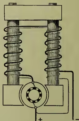
An important element in the classification of dynamos is the manner in which magnetism is induced in the field-magnets. These may of course be excited from an independent source of electricity; but when the machine is self-exciting, there are three important alternative methods. In the early machines the coils on the field-magnets were connected in series with the external part of the circuit, and consequently the whole current produced by the machine passed through both. This arrangement is distinguished as series winding, and is shown diagrammatically in fig. 8. It was first pointed out by Wheatstone, in 1867, that the magnet coils, instead of being put in series with the external conductor, might be arranged as a shunt to it, thereby forming an alternative path through which a portion only of the current would
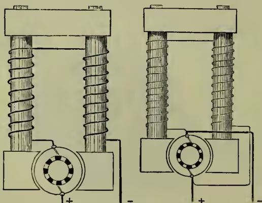
Fig. 9.
pass. In this arrangement, which is called shunt winding (fig. 9), the magnet coils consist of many turns of comparatively fine wire, so that they may not divert an excessive quantity of current from the external circuit. Finally, in compound winding (fig. 10) the two previous methods are combined. The field-magnets are wound with two coils; one of these (which is short and thick) is connected in series with the external circuit, and the other (which is long and fine) is connected as a shunt to it. This plan appears to have been first used by Varley in 1876, and afterwards by Brush, who pointed out that it, along with simple shunt winding, has the advantage of maintaining the magnetic field even when the external circuit is interrupted. It has, however, when properly applied, another and more important merit, as will appear below.
In a series-wound dynamo the magnets do not become excited if the external circuit is open, and become only feebly excited when the external resistance is high. Let the external resistance be reduced, while the armature is forced to turn at the same speed. The current will now increase, producing a stronger magnetic field; the electromotive force is therefore greater than before. A curve drawn to show the relation between the current and the difference of potential between the terminals of the machine (which is a little short of the full electromotive force, in consequence of the resistance of that part of the circuit which is within the machine itself) will in its
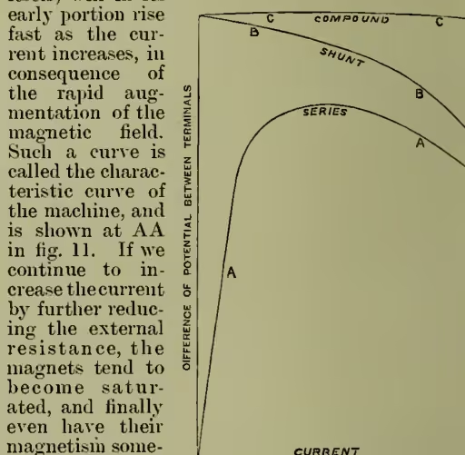
early portion rise fast as the current increases, in consequence of the rapid augmentation of the magnetic field. Such a curve is called the characteristic curve of the machine, and is shown at AA in fig. 11. If we continue to increase the current by further reducing the external resistance, the magnets tend to become saturated, and finally even have their magnetism somewhat weakened on account of the influence of the currents in the armature coils. Further, the loss of potential, through internal resistance, becomes more considerable. The difference of potential between the terminals accordingly passes a maximum, and becomes considerably reduced when the current is much augmented, as appears in fig. 11. The characteristic curve for a shunt-wound dynamo is shown at BB in the same figure. Here the strength of the magnetic field is nearly constant, but decreases a little when the machine is giving much current, partly because the current in the shunt circuit is then somewhat reduced, and partly because the current in the armature coils tends to oppose the magnetisation. Hence the potential falls off as the current increases. This fall will, however, be slight if the resistance of the armature is very low and if the field-magnets are very strong, and under these conditions a shunt-wound dynamo will give a nearly constant difference of potential whether much or little current be taken from it, provided, of course, that the speed remain unchanged. To make the difference of potential more exactly constant, it is necessary that the magnetic field should become stronger when the machine is giving much current, and compound winding achieves this. A compound-wound dynamo may be regarded as a shunt machine in which the action of the shunt winding is supplemented by that of a series coil on the magnets. When the machine is running on open circuit, the shunt coil alone is operative; as the current taken from the machine is increased, the series coil produces a larger and larger supplementary effect on the magnets, and by choosing a proper number of series windings, their effect may be made to neutralise with great exactness the droop in the characteristic curve which would occur if the shunt coil were the only source of magnetism. Compound machines wound for constant potential give a nearly straight horizontal line for their characteristic; CC in fig. 11 is an actual example. By making the series coil more influential, so that the potential at the terminals rises slightly as the current increases, the machine may be compound-wound to give constant potential at the ends of long leading-wires by which the current is conducted to a distance.
Series-wound dynamos are largely employed for electric lighting by arc lamps. Compound-wound machines are especially suitable for incandescent lighting, where the lamps are connected in parallel, and where it is important that the potential shall not vary when more or fewer lamps are in action. Shunt-wound machines are also largely used for incandescent lighting, the potential being adjusted to a constant value by varying the speed of the machine, or by throwing resistance into or out of the magnet shunt circuit. Shunt machines are the most suitable for charging storage batteries and for electro-plating, because of their not being liable to have their polarity reversed by a back current from the battery or bath.
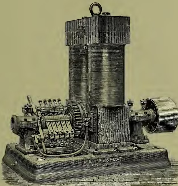
Fig. 12 illustrates the Edison-Hopkinson dynamo, which may be cited as an excellent instance of modern construction. Here a drum armature is used, not a ring; and in this instance the armature coils, instead of being of wire as they are in smaller machines, are formed of copper bars insulated with mica, each pair of opposite bars being joined to form a loop, the ends of which are connected to opposite segments of the commutator, as well as to the loops which come next in order. The field-magnets are shunt-wound, and are set vertically with the pole-pieces at the bottom. Machines of this class are made of sufficient size to give a current of 660 ampères, with a potential of 105 volts; the output of electrical energy is therefore at the rate of 69,300 watts, or over 92 horse-power. There are five brushes on either side of the commutator, giving a large area of contact, and these are separately removable to allow of their being trimmed or cleaned while the machine is running.
In most dynamos the field-magnets are designed to form as simple a magnetic circuit as possible, with two poles which stand at opposite ends of one diameter of the commutator. In some cases four or more poles are used, spaced at equal intervals round the armature, which then takes more or less the form of a disc, in which the similarly affected coils may be connected together, so that a single pair of brushes still serves to take off the current. In some cases the coils are connected to commutators of special design, which have the effect that each coil is entirely cut out of circuit for a time, during that part of its movement in which there is little or no electromotive force induced in it. The Brush dynamo, which took a prominent place in the early industrial development of electric lighting, and the Thomson-Houston dynamo, are instances in point.
In alternate current dynamos the armature consists usually of a group of coils, joined in parallel or series, attached to a disc which revolves in the space between a corresponding group of pairs of magnet-poles, so that rapidly alternating transient currents are induced as the coils pass the successive poles, and these currents pass to the external circuit through a simple collector which is not a commutator. In some cases the armature is stationary, and the field-magnets revolve. The field is usually excited by an auxiliary dynamo of the continuous current type. It is impossible in the space at our disposal to describe the great variety of forms which alternate current machines have taken in the hands of Siemens, Gordon, Ferranti, Westinghouse, Mordey, and others. Dynamos of this class are now acquiring a special importance from their use in connection with transformers in Electric Lighting (q.v.), and are being made for this purpose of very great size and power. In alternate current dynamos, the relation between the strength of the current and electromotive force induced in the moving coils depends not merely on the resistance of the circuit, but also on its coefficient of self-induction, which has the effect of making the maximum of strength in each transient current lag behind the maximum of electromotive force. It has been shown experimentally and theoretically, by Adams and Hopkinson, that in consequence of self-induction two similar alternate current machines driven independently, but started at the same speed, and connected in parallel, will control one another, so that the phases of the currents will continue to agree.
Dynamos, of whatever type, may be regarded as machines for converting energy from a mechanical into an electrical form, and from this point of view a matter of prime importance is what is called the efficiency of the machine, which is the ratio of the electrical power the dynamo gives off, available for use outside the machine, to the power used to drive the machine. The electrical energy given off falls short of the mechanical energy absorbed, in consequence of (1) mechanical friction; (2) the generation of eddy currents, to be prevented as much as possible by laminating the iron core of the armature; (3) magnetic friction or 'hysteresis,' by which every reversal of magnetism in the iron causes dissipation of energy, apart from the production of eddy currents; (4) the energy consumed in maintaining the magnetic field; and (5) the heating of the armature in consequence of the resistance of its own coils. The aggregate effect of these sources of loss is that in a good machine about 90 per cent. of the driving power is available as electric energy in the external circuit. Dr Hopkinson has shown by careful measurements that machines of the type illustrated in fig. 12 may attain an efficiency of over 93 per cent.
The Dynamo as a Motor.—Just as a conductor when made to move across the lines of magnetic force has a current generated in it, so when a current is made to pass along a conductor placed in a magnetic field, the conductor tends to move across the field in the direction which would reduce the current by inducing an opposing electromotive force. Even before Faraday's discovery of the induction of current in a conductor by its movement in a magnetic field, he had shown (in 1821) that the reverse process was possible, and soon afterwards various forms of magneto-electric engines were devised by Barlow and Sturgeon, and later by Ritchie, Henry, Dal Negro, Joule, and others, which employed electric currents to do mechanical work on a small scale. In 1838 Jacobi constructed an electric motor of sufficient power to propel a small boat, using a group of electro-magnets, which revolved on a disc between opposite groups of other electro-magnets, which were fixed. Some time before the application of the ring-armature to dynamos by Gramme, it had been used in a motor by Pacinotti, and the principle had been explicitly stated that any electric motor might be used to produce currents, but it was not until Gramme's time that the full significance of this principle was generally recognised. The action of the dynamo is in fact reversible; the same machine which converts mechanical into electrical energy will serve the opposite function equally well. Power may therefore be conveyed to any distance by using a dynamo to produce currents, conducting these to the distant spot, and utilising them there to produce mechanical effect by means of another dynamo acting as a motor. The second dynamo may be a counterpart of the first; in some cases, however, it may be desirable, for the sake of lightness or for other special reasons, to adopt a different construction in the motor. In general, however, the most efficient generator is also the most efficient motor. The experiments of Hopkinson, in a case where some 50 horse-power was being transmitted in this way, show that the double conversion of energy from the mechanical to the electrical, and back again to the mechanical form, may be accomplished with a total loss of no more than 13 per cent.; the efficiency of the motor and that of the generator being each above 93 per cent.
Alternate current dynamos form fairly efficient motors when driven by alternate currents; they require to be started in synchronism with the impulses received from the generating machine, but once started they tend to remain in synchronism. Many special forms of motor for alternate currents have been designed.
See ELECTRIC LIGHT, ELECTRIC RAILWAY, TRAMWAYS; and for the utilisation of water-power, ALUMINIUM, FOYERS, NAGARA. On the theory of dynamos, see papers by J. Hopkinson (Proc. Inst. Mech. Eng. 1879-80), in which were explained the construction and uses of curves, such as those of fig. 11 (afterwards called characteristic curves by Deprez); by J. and E. Hopkinson (Phil. Trans. 1886), in which it was shown how the strength of the field and the performance generally of a dynamo might be predicted by calculation of the induction in the magnetic circuit of the machine; by Joubert (Jour. de Physique, 1883), on alternate current machines; and by Ayton and Perry (Jour. Soc. of Telegraph Engineers, 1883), on the regulation of motors. See articles in the Electrician, the Electric Review, and Engineering; S. P. Thomson, The Electro-Magnet (1891), and other books; and works by Urquhart (1891), Fleeming Jenkin (new ed. 1892), Kapp (1892), Hopkinson (1893), and Hawkins and Wallis (1893).