Hydrodynamics, in its complete generality, is the science which treats of the motions and equilibrium of a material system, part or all of which is fluid. In accordance with modern dynamic nomenclature (see DYNAMICS) we should discuss it under the two headings Hydrokinetics and Hydrostatics. The historic usage of the term has, however, so fixed itself that we generally regard hydrodynamics as excluding hydrostatics and as dealing only with kinetic problems. Originally, as the derivation of the words at once show, hydrodynamics and hydrostatics referred only to the motion and equilibrium of liquids; but as our knowledge of the physical properties of all kinds of fluid, liquid and gaseous, increased, it was recognised that they had much in common from a dynamic point of view, and the terms became extended in their application as defined above. Thus the floating of a balloon in air depends on the same hydrostatic principle as the floating of a ship on water. The simpler and some of the more practical problems of hydrostatics will be found treated under that heading. In its practical engineering aspects hydrodynamics is known as hydraulics, including such important subjects as the construction of canals, breakwaters, docks, pumps, water-pipes, water-wheels, and so on, most of which have separate articles to themselves. Here we shall confine ourselves to the scientific principles of the subject, using familiar cases as illustrations.
The study of hydrodynamics has led to the conception of what is called the perfect fluid. It may be defined as a substance incapable of resisting the smallest deforming stress. For instance, no portion of such a fluid can resist, even for a moment, a longitudinal pressure if unsupported by a lateral pressure. The logical consequence of this definition is that, if the fluid is at rest, the pressure at a point is the same in all directions; for if it were not so there would be a deforming stress, and therefore a yielding of the fluid, and equilibrium could not exist. By similar reasoning we may show that, if the pressure varies from point to point in a fluid at rest, there must be an external force acting on the fluid in the direction in which the pressure is increasing. Thus, in virtue of gravity, atmospheric pressure decreases as we ascend, and the pressure in the ocean or any other body of water increases as we descend. So long as we are dealing with equilibrium of fluids we meet with nothing inconsistent with the definition of the ideal perfect fluid. Across every interface separating two contiguous portions of the fluid the mutual stress is of the nature of a pressure wholly normal to the interface.
When, however, we pass to cases of fluid motion we find that the properties of the perfect fluid are very far from being realised in nature. The smallest relative motion amongst the different parts of a fluid brings into play mutual stresses which are not normal to the interface between two contiguous portions. These tangential stresses tend to destroy the relative motion, existing only so long as the relative motion exists. They are thus partly analogous to resistances due to friction in the dynamics of solid bodies—hence the term fluid friction (see VISCOSITY) frequently employed to denote the property that discriminates actual fluids from the ideal perfect fluid. Fluid friction, however, differs from friction in one marked particular; it has no significance in static problems. It is wholly kinetic. The gradual stilling of troubled waters, the calming of the wind, the slackening in speed of the water in a stream as we pass from the centre and surface portions towards the banks or bottom are familiar examples of the effects of fluid friction.
Under certain circumstances the tangential stresses thus brought into play not only retard the motion of the more swiftly-moving parts of the fluid, but even accelerate the motion of the more slowly-moving parts. Thus a rapidly-flowing river entering the sea draws along with it a considerable quantity of the original ocean water. The effects of a draught of air are felt far beyond the direct course of the main current. It is impossible, in fact, to mark off clearly the boundaries of a current flowing in fluid of the same kind. In like manner, the eddies formed in the wake of a solid body moving through either air, water, or other fluid could not be produced if it were not for the existence of these tangential stresses. In every case the final result is a dissipation of energy (see ENERGY); but in the majority of cases of practical importance the rate of dissipation is so slow—in other words, the tangential stresses are so small in comparison with the other effective forces acting—that the properties of the perfect fluid go far to explain many hydrokinetic phenomena. Some of these we shall now consider.
It has been already pointed out that the equilibrium of a fluid under the action of gravity or other force depends upon the manner in which the pressure varies in the direction of the force. Now a force has always a definite direction; and consequently in all directions perpendicular to the direction of the resultant force acting at a point in the fluid there can be no variation of pressure. Thus, from any one point we can pass to an infinity of neighbouring points at which the pressure is the same; from each of these again to an infinity of others; and so on indefinitely. We thus arrive at the conception of a surface in the fluid, at every point of which the pressure is the same. Such a surface is called a surface of equal pressure, and one of its essential properties is that it is perpendicular at every point of it to the resultant force there. In the case of fluids at rest under the action of gravity these surfaces are also called level surfaces, and are for all practical purposes essentially horizontal planes. A consideration of these principles leads easily to the conclusion that equilibrium in a fluid mass cannot exist if the pressures at two points at the same level differ, or if the pressures are the same at two points at different levels. These two conditions are essentially one and the same; and when they are fulfilled, fluid motion must take place (see such articles as ATMOSPHERE, WIND, WAVE, SIPHON, and ARTESIAN WELLS for familiar illustrations of these principles).
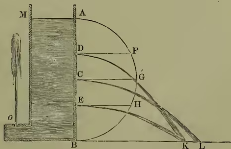
The discharge of fluids through orifices includes a number of very important phenomena, some of which we shall discuss in detail. The vessel MAB (fig. 1) is provided at D, C, E, o with apertures which may be closed when desired. Let the vessel be filled with water up to the level MA; then, if the orifice o, which looks vertically upwards, is opened, a jet of water will be projected up, and will reach very nearly to the height MA. If it were not for fluid friction and the consequent dissipation of energy the jet would reach the height MA. As soon as the orifice o is opened, the water surface there being exposed simply to the pressure of the atmosphere is under the same pressure as the much higher surface MA. Hence a flow takes place and will continue to take place until the surface of the water MA has sunk to the level of the water at . The experiment shows that the jet is projected with a velocity very nearly equal to that which would be acquired by a body falling under gravity from the level AM to the level . This velocity is given by the relation , where is the acceleration due to gravity and the difference of level mentioned. Similarly, if the orifices at D, C, E are opened, the issuing jets will be projected with speeds whose squares will be found to be very approximately proportional to the differences of level between the upper surface MA and the respective orifices. This may be proved experimentally by constructing the orifices so that the discharge is initially horizontal, and then measuring the range, BK or BL, reached by the several jets. Thus, assuming the law just given, commonly called the theorem of Torricelli, we may show that the square of the range BK is equal to four times the product of the differences in level of the orifice D below A and above B, that is, . Hence if we describe a semicircle AGB on AB as a diameter, the horizontal lines DF, CG, EH meeting this semicircle will be half the horizontal ranges corresponding to the respective orifices.
The height of the free water surface above the orifice from which the water is issuing is technically called the head. The greater the head the greater is the pressure at the level of the orifice, and the more available the water for practical purposes. Part of the head is consumed in overcoming frictional resistances; for well-formed simple orifices about 64 per cent. of the whole head is so expended. The discharge from any orifice in a given time will depend obviously on the size of the orifice and on the available head. Experiment shows, however, that for sharp-edged orifices in a wall the discharge is distinctly less than the simple theory would indicate. In such cases the section of the jet is smaller than the section of the orifices in the ratio of about 5 to 8. This is sufficiently explained by the convergence of the streamlets in the fluid which ultimately form the jet; and this convergence continues for a little distance beyond the orifice, producing the phenomenon of the vena contracta or contracted vein. We have seen how the speed of efflux is measured by means of the parabolic path of the jet; this speed multiplied by the number of seconds in a chosen interval of time, and by the effective (unknown) area of the orifice gives the whole discharge in that interval. This discharge can be easily measured; and thus the data are complete for finding the effective area of the orifice and comparing it with the real area. By furnishing an orifice with a short mouthpiece of the form of the contracted vein, we may regard the smallest cross-section of the mouthpiece as the true orifice. In this case the effective area and the real area are the same.
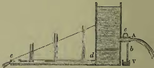
In these simple cases of efflux the energy of efflux is wholly explained as being derived from the hydrostatic head of water. The pressure due to this head is the weight of a column of water of unit-cross-section and of a height equal to the head. Thus, if is the density of the water, so that is the weight of unit-volume, the pressure due to a head is . Thus, by Torricelli's theorem, is half the square of the velocity with which a jet would be projected through an orifice made at a place where the pressure is . Hence we may regard this ratio as the energy per unit-mass of water due to the pressure . But if the water is in motion with a speed , its energy per unit-mass is on this account . If, further, the particular portion of the fluid considered is at a height above a certain arbitrarily chosen level, defined as the level of zero potential energy, then its potential energy is . The whole energy possessed by the moving fluid is built up of these three parts due respectively to pressure, speed, and gravitation, and is given therefore by the expression . Now, in the case of a steady frictionless flow along a determinate channel, the whole energy possessed by any unit-mass of the fluid must be the same; for at some time or other every element passes through the positions occupied at other times by other elements in the same streamline, and passes through them under the same dynamic conditions. Hence, neglecting the effects of friction, we arrive at the conclusion that the expression for energy just given is constant along any given stream-line. Take, for example, a pipe of uniform bore. If the flow is steady the invariableness of the cross-section requires the speed at every point to be the same. Hence as diminishes must increase, so that may remain constant. For a horizontal pipe must be constant, and so of necessity is . Now suppose the tube to be horizontal but of variable section; then, since is constant, the expression must also be constant. But the speed varies inversely as the section; hence must be greatest where the bore is widest and least where the bore is narrowest. In other words, the cross-section and pressure increase together and diminish together. A familiar illustration of this is shown in fig. 2, in which water is escaping from a short cylindrical nozzle A. The contracted vein occurs at , so that, the velocity being greater there than at the open end of the tube, the pressure is less. But the pressure at A is the atmospheric pressure; and, consequently, if a tube be led from to the vessel of water V, the water will be pushed up to some point by the excess of the atmospheric pressure over the pressure at .
When the effects due to friction are taken into account we see in a general way that the energy, instead of remaining constant as we pass along a stream-line, will steadily fall off. In the case of a uniform pipe this loss of energy will show itself in a more rapid falling away in the pressure. For instance, in a horizontal pipe of uniform bore the pressure will steadily diminish as we pass along in the direction of the flow. At the open end of the pipe (, fig. 2) the pressure is that of the atmosphere; and this will gradually increase as we pass along the pipe against the flow until we come to , where the pressure falls a little short of that due to the head of water in the vessel. This may be shown experimentally as indicated in the figure, in which the small upright tubes inserted in the horizontal pipe become filled with water to a certain height. In the construction of water-works these and many other problems in hydrokinetics receive their practical solution. In the motion and flow of highly compressible fluids, such as gases, we meet with theorems similar to those just discussed for liquids. The treatment, however, is necessarily more abstruse, and is far from complete if thermodynamic considerations are left out of account. See GASES, SOUND, THERMODYNAMICS.
The hydrokinetic problems connected with the motion of solids through fluids have their most important applications in questions which concern the artilleryman and the shipbuilder. In the practice of gunnery the law of the resistance to projectiles in air has been very fully worked out. At very high speeds the resistance is very great indeed; and it may be shown that an ordinary-sized projectile if dropped from an immense height (say 40 miles) could never, under the action of gravity alone, attain a speed of 800 feet per second. One great source of loss of energy of a body moving through a liquid is the formation of eddies and vortices in its wake. These are the direct result of tangential stresses acting between contiguous portions of the fluid moving with different speeds. In virtue of the same tangential stresses the eddying motions quickly die away, and the energy, as in all such transformations, takes the form of heat.
The best English treatises on hydrodynamics are Lamb's Hydrodynamics (1895) and Bassett's Hydrodynamics (2 vols. 1888-89); see also Unwin's 'Hydraulics' in Encyclopedia Britannica (9th ed.).