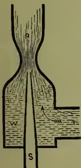
Injector. Fig. 1 shows in section a simple form of injector for raising water. Steam issuing from the pipe S, into the vessel WR, will first create a partial vacuum above W by dragging air with it, and then, when the water-level is above the nozzle, will, on collapsing by condensation, impart its energy to the water and drive it up through the narrow neck below R, to a height of about one foot for every pound of steam-pressure per square inch. It is doubtful whether these injectors can work so economically, as regards expenditure of steam, as ordinary slow-moving pumps do; but they possess many conveniences and advantages which are bringing them into use.
Feed-pumps, for feeding water into steam-boilers, are difficult to keep in order when driven at high speed. The very rapid action of the valves severely tries their durability. In the case of locomotives inconvenience was often occasioned by the fact that their feed-pumps acted only when they were running; and thus, if an engine happened to stand still for any length of time, the water occasionally got too low in the boiler. M. Henri Giffard's injector, now in general use in place of high-speed feed-pumps, acts equally well whether the engine is running or at rest.
The diagram fig. 2 will give an idea of the essential parts of Giffard's injector. A is the steam-boiler, B the water-level, CDF a pipe into which steam is admitted: this pipe terminates in a cone DF, which is enclosed in a larger cone HH. In the cone DF the pointed plug E can be raised or lowered so as to increase or diminish the area of the aperture at its lower end F. G is a pipe communicating with the water-cistern, and admitting water into the external cone HH. K is a pipe communicating with the boiler under the water-level. On opening communications between the boiler and this apparatus it might be expected that steam would rush out at F, and water at K, both currents meeting with great force, and escaping into the atmosphere between the two openings.
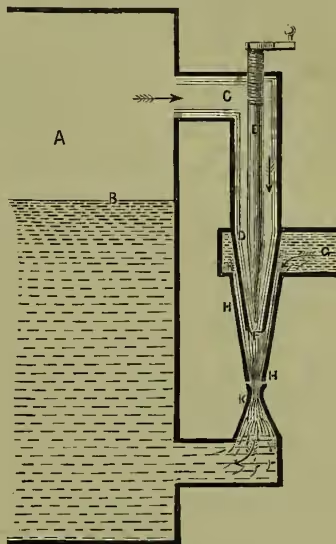
Paradoxical as it may appear, the water at K, although it is actually, by reason of the head of water arising from the difference of level between the aperture at K and the water-level at B, subject to a greater boiler-pressure than is the steam in the cone DF, is yet overpowered, and driven back into the boiler by the stream of water and condensed steam issuing from H; and thus water, from the pipe G and the tender or cistern, is introduced into the boiler, and constitutes the feed-water. The energy of the collapsing steam at F is transferred to water in HH; this is driven forward in a stream, which is at its narrowest at K; in this stream the actual energy per unit of bulk at K thus comes to exceed the potential energy of the boiler-water at K, and its actual velocity to exceed the possible velocity of outflow from K; whence the outflow from K is overpowered. In practice this injector is a somewhat expensive apparatus in consequence of the number of adjustable parts required. Variations in the pressure of steam require alterations in the area of the steam-passage, and in the distances between the mouths of the conical openings for the outflow and inflow of steam and water.