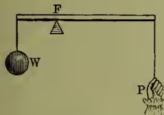
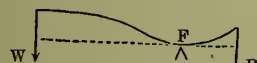
Lever, an inflexible rod—straight or bent, as the case may be—supported at some point of its length on a prop which is called the fulcrum, and having a resistance to be overcome and power to overcome it applied at other two points. The general principle governing levers of all sorts is that the power and the resistance must tend to produce opposite rotations round the fulcrum, and that their moments—the product of either of them into the shortest distance between the line of the application and the fulcrum—must be numerically equal; or, in other words, the power and the resistance are in the inverse ratio of their respective shortest distances from the fulcrum. When this is the case there is equilibrium; when either 'moment' predominates there will be rotation. fulfilled whether the power P, the fulcrum F, and the resistance W stand in the order PFW, PWF, or WPF; and hence levers are popularly divided into three classes. In the first class (PFW)—fig. 1 for a straight lever, fig. 2 for a bent one, equivalent to a straight lever since P and W are parallel—we have the Balance (q.v.), the spade (when used for raising earth), the seesaw; or, as double levers, scissors and pincers.
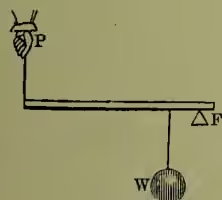
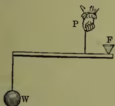
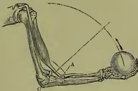
In the second class (PWF, fig. 3) we have crowbars (P the hand, W the resistance of the body pushed, F the ground), boat-oars (P the hands, W at the rowlock, the resistance of the boat, F the comparatively fixed position of the oar-tip in the water), wheelbarrows; and, as double levers, nutcrackers (P the hand, W the nut, F the hinge). In the third class (WPF, fig. 4) we have fishing-rods, whips, umbrellas, and most instruments used with the hand alone, and coal- and sugar-tongs; and many instances in the muscular system—e.g. the biceps muscle and forearm of man (fig. 5), his deltoid muscle and shoulder, the pectoral muscle and wing of birds.
Lever, Charles, a popular novelist, chiefly remembered for the rollicking fun of his Irish stories, was born in Dublin, 31st August 1806. He graduated at Trinity College, Dublin, in 1827, and then removed to Göttingen, where he studied medicine, and subsequently returned to Dublin to complete his academic career. His most popular work, Charles O'Malley, is a reflex of his own college life in Dublin, and many of the incidents in the novel, as in many of his late productions, are drawn from his own experiences of the world. Probably in 1824, and certainly at some time between 1827 and 1832, he spent a considerable time in the backwoods of Canada and North America, and subsequently embodied his experiences in Con Cregan and Arthur O'Leary. Returned to Ireland, he practised medicine first at Kilrush in County Galway, and afterwards at various other country towns, collecting material for his stories of Irish country life. Having married a Miss Baker, he went in 1837 to practise medicine at Brussels, and while there wrote Harry Lorrequer, and afterwards Charles O'Malley for the Dublin University Magazine, then recently started. Returning to Dublin, he published Jack Hinton in 1841, and from 1842 to 1845 acted as editor of the Dublin University Magazine, and wrote Nuts and Nutcrackers, Arthur O'Leary, Tom Burke of Ours, and The O'Donoghue. In 1845 he again went off to the Continent, going first to Brussels, then to Bonn and Carlsruhe, where he lived for some time, and published the Knight of Gwynne. He then moved on to Florence, and wrote Roland Cashel, and thence to Spezzia, where Luttrell of Arran, Con Cregan, Sir Jasper and he is thus able to exert his full muscular strength.
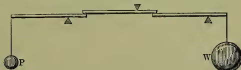
When a large mechanical advantage is required this may be obtained, without using bars inordinately long, by means of a combination of them (as in fig. 6). Here the levers have their arms in the ratio of 3 to 1, and a little consideration will make it plain that a power, P, of 1 lb. will balance the weight of 27 lb. But in this instance the particular defect of the lever as a mechanical power shows itself prominently; for if the 27 lb. mass has to be lifted two inches, the power requires to act downwards through ; and, as the extent of sweep of the power cannot be largely increased without inconvenience, the advantages of this contrivance are confined within narrow limits.