Lock, an arrangement for fastening doors, drawers, &c., and requiring a key or other similar contrivance to open it. The early Egyptians used locks of rude construction, generally made of wood; and locks and keys of bronze and iron have been found in large numbers in Pompeii and Herculaneum. Fig. 1 represents the ancient
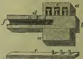
Egyptian lock in section: a is the case, fastened to the door; b, the bolt; in the upper part of the case are three openings, c, each containing a pin with a head to prevent its falling too far down. When the bolt is pushed home towards b, the pins fall into the corresponding three holes, d, preventing its being withdrawn. The key is a piece of wood, e, which is pushed into the opening, f, in the bolt, and by means of its three pins the pins in the case are pushed up while the bolt is withdrawn. An exactly similar lock is still used in the Faroe Islands, and one very like it in St Kilda. The Chinese for many hundred years have had a much superior wooden lock with tumblers.
During the 15th, 16th, and 17th centuries very ingenious and complicated locks, richly ornamented with hammered iron-work, were made, especially in Germany, and in every collection may be seen more or less fine specimens. These, however, were necessarily very expensive, and could only be used by the wealthy, and the lock in ordinary use up to the beginning of the 19th century was the common
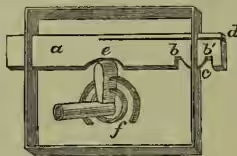
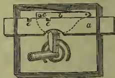
spring-lock shown in fig. 2, and which is still used for ordinary purposes. The bolt, a, passes through an opening in each side of the case, and is held in position by the two notches, b, b', which are pressed against the bottom of the opening, c, by the spring, d, as the bolt is locked or unlocked. The key, acting in the semicircular notch, e, in the bolt, pushes it either to one side or the other as required; the fig. represents the bolt midway between open and locked. Certain notches in the key fitting into corresponding wards, f, fastened to the plate of the lock, are supposed to prevent any other instrument but its own key from opening the lock. The first improvement on this was the common tumbler-lock (fig. 3), which represents the simplest form of it: a is the bolt; b, the tumbler, with a projection, c, which is pressed by the spring, d, into the notches, e, e, according as the lock is open or shut. The key, by the one movement, raises the tumbler and moves the bolt.
Barron's lock, patented in 1778, was a development of the tumbler principle. By putting the notches in the centre of the bolt instead of on the top edge, the pin in the tumbler had to be lifted to an exact height to pass the bolt, rendering it much more difficult to pick. Barron subsequently added a second tumbler which had also to be passed by the bolt. Barron's form of construction is still in use, and it may be considered the parent of the modern many-tumbler or lever lock, of which Moses Bird's (1780) was the first.
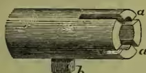
The lock patented by Joseph Bramah in 1788, and still one of the recognised best locks for certain purposes, is of a different construction. An inner barrel turning inside a fixed cylinder has a central pin on which the key works. The key (fig. 4) is a simple pipe with generally four slits, a, a, and a pin, b; when it is inserted and pressed down, the slits press on corresponding slides working in the inner barrel, till, arriving at a certain point, the barrel is released and can be turned round by the pin, b; another pin on the barrel moves the bolt. A spiral spring on the central pin keeps the slides in their original position till pressed down by the key. The varying depths of the slits in the key agree with the distance which the different slides have to be pressed down; and, as no two locks are alike in this respect, each key can only open its own lock. So much confidence had the Messrs Bramah in this lock that during the Great Exhibition of 1851 they offered a prize of two hundred guineas to any one picking it, which prize was gained by Mr Hobbs, an American, who occupied fourteen days in devising and making tools, and fifty-one hours actually at work on the lock.
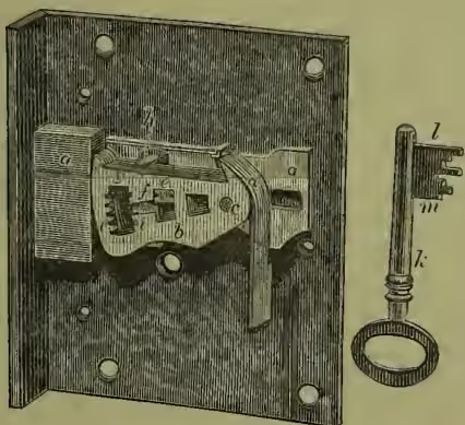
Chubb's lock, originally patented in 1818, is a further development of the many-tumbler principle. It is shown in fig. 5, which represents it unlocked, and with the inner plate removed the better to show the movement: a is the bolt; b, the tumblers, six in this instance, which move independently on the common pin, c, each having one of the six springs, d, to keep it in position. The stump, e, riveted to the bolt, must pass through the gate, f, in all the tumblers before the bolt can be shot. As this gate is in a different position in every tumbler, they must be raised to correspondingly different heights before they coincide for the stump to pass. For this purpose the key, k, has different steps so arranged that, when it is turned in the lock, each step raises its own tumbler to the proper height, and the step nearest the end of the key, l, shoots the bolt; the stump passing through the coinciding gatings and slipping into the space, g, as the tumblers, released by the key, resume their original position. In opening the lock the reverse of this movement takes place. A pin, h, fixed on the backmost tumbler and reaching over the tops of the others is called the detector. Should any false key be tried in the lock when locked, or any other means used which should raise either of the tumblers too high, an ingenious arrangement fixes it so that the lock is obstructed and cannot be opened, even with its own key, till the fixed tumbler is released. This is done by making an extra forward movement of the key, when the tumbler will resume its normal position. This detector movement is intended as a precaution against burglars, and also to record any attempt to pick the lock. False notches, i, i, are made in the tumblers to defeat attempts to pick the lock by feeling for the different gatings by backward pressure of the bolt applied by ingenious instruments—a method, difficult as it may seem, which has been successfully used against all tumbler-locks, unless specially safeguarded. A movable circular curtain attached to the keyhole in the inner plate is moved by the aftermost step of the key, m, as it is turned round. This prevents an inspection of the tumblers for picking purposes by means of a reflector introduced into the keyhole, while they are moved by any instrument, as nothing can be turned round in the lock without also turning the curtain.
Hobbs's protector lock has a series of tumblers as in Bird's and Chubb's locks, but, in addition, has what is termed a protector, shown in fig. 6. It consists of a shaped lever, a, b, working on the pin, c, which is riveted into the bolt, A, and it is kept in position by the friction spring, e. The stump, b is fixed to the protector, and, passing through a hole in the bolt, acts on the tumblers (not seen in the fig.) at the other side of the bolt.
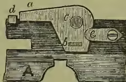
This arrangement entirely prevents feeling for the gatings of the tumblers by pressing back the bolt. If any attempt is made to push back the bolt when locked, it only moves the protector enough to bring down the long arm, a, in front of the pin, d (fixed in the back plate of the lock), as shown in the fig. This prevents any further movement of the bolt till the protector is set free by a slight turn of the proper key. This lock, when in combination with another ingenious arrangement called the revolving nozzle, which prevents tampering with false keys, has successfully resisted all attempts to pick it.
Lord Grimthorpe (formerly Beckett-Denison) invented a modification of the tumbler-lock which locks with a handle, only requiring a small key to open it. The keyhole is so narrow that no instrument strong enough to injure the lock can be introduced. It has other advantages, and its inventor claims that it is unpickable. It has not been patented. He is also the inventor of a dust excluder for the key-holes of locks, operated by a spiral spring.
Many other varieties of the tumbler or lever lock have been invented which we have not space to describe.
Combination locks are sometimes used for burglar-proof safes. In these locks the tumblers are represented by wheels, generally four in number, which can be turned independently in connection with an index on the outside of the safe. The lock can only be opened by making certain movements of the handle on the index, which cause the gatings in the wheels to coincide. The combination of numbers on the index with the different wheels can be altered at pleasure, and, of course, the lock can only be opened by those knowing this combination. The weak point of this lock is that the combination may be forgotten. The Yale time-lock is an improvement, by Mr Yale of Philadelphia, on the time-lock invented by Rutherford of Jedburgh, Scotland, in 1831. A watch in combination with the lock may be set so that the lock can only be opened at a particular hour even by the owner.
Changeable-key locks were first introduced into England by Mr Hobbs, who brought Day and Newell's paraautoptic lock to London in 1851. After many improvements, Mr Hobbs perfected this lock in 1862, and in 1865 the firm of Hobbs, Hart, & Co. introduced a simpler and cheaper form of it. By an ingenious modification of the tumblers, which we have not space to describe, the lock may be locked by any one of a great number of keys, but can only be opened by means of the one which locked it. Some of these locks afford a possible choice from about 60,000,000 keys, any one of which will lock it, and which must be used to open it again. To avoid the necessity of having a number of keys, different webs are supplied which fit on the key-pipe to form the key. The webs may be kept in the safe, one taken out at random to lock up with; the web removed from the key carried away in the waistcoat pocket, and the key hung up anywhere, useless till the web is brought back.
In the ordinary safe locks the bolts are necessarily on a large scale, and, to prevent the carrying about of a key of corresponding magnitude, the bolts are usually shut by means of a handle, and a small lock with a small key locks one of them and fastens them all.
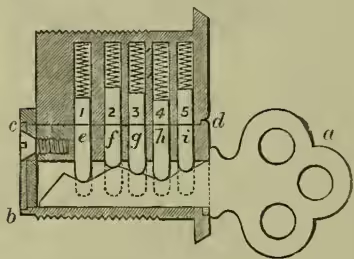
Latch-locks used on street doors which shut of themselves, and are opened by means of a handle d is a movable barrel turning inside the lock; 1, 2, 3, 4, 5 are five pins pressed down by spiral springs working in holes in the fixed part; e, f, g, h, i are five corresponding pins moving in holes in the inside barrel; they are of irregular lengths, and when the key is out, e, f, g, h, i drop down, as shown by the dotted lines, allowing 1, 2, 3, 4, 5 to drop into the holes in the barrel, fixing the lock. As the key, which has indentations exactly corresponding with the varying lengths of e, f, g, h, i, is pushed in, it raises those pins till they and 1, 2, 3, 4, 5 coincide at the junction of the barrel and the fixed part of the lock. The barrel may then be turned and a pin on it shoots the bolt, not shown in the fig. The key is a thin piece of tempered steel weighing only a small fraction of an ounce, and the keyhole correspondingly narrow.
Locks made for various purposes, such as doors, drawers, writing-desks, portfolios, cupboards, &c., however differing in arrangement, are all constructed on the same principle. The padlock, in which the lock is a separate arrangement, is precisely similar to other locks except in shape. It has also a movable bow which is hooked into a staple or other fastening and then locked.
Locks for drawers, cupboards, and the like, which only require to be opened on one side, are generally made with a central pin on which the key, with a pipe, works; but in locks which must be opened from both sides this arrangement is impossible, and the key is solid, working through a hole in the lock. It must, however, be symmetrical, so as to exactly reach the turning place of the lock from either side. Locks which are mortised into the thickness of the door are called mortise locks.
Many ingenious automatic latches have been invented for cabinets and the like, which shut of themselves when the door is closed, and can be pulled open without a key or turning a handle; they are used when security is not required, only a means of keeping the door closed.
See Price's Treatise on Locks and Keys (1856); Sir E. Beckett (Denison), Treatise on Locks; Hobbs and Tomlinson, Treatise on the Construction of Locks (new ed. 1868); and G. H. Chubb, Protection from Fire and Thieves (1878).