Microscope (Gr. mikros, 'small;' and skopeo, 'I see') is an instrument for enabling us to examine objects which are so small as to be almost or quite undiscernible by the unaided eye. Its early history is obscure; but, as it is quite evident that the property of magnifying possessed by the lens must have been noticed as soon as it was made, we are quite safe in attributing its existence in its simplest form to a period considerably anterior to the time of Christ. It is generally believed that the first compound microscope was made by Zacharias Jansen, a Dutchman, in the year 1590, and was exhibited to James I. in London by his astronomer, Cornelius Drebbel, in 1619. It was then a very imperfect instrument, colouring and distorting all objects. For many years it was more a toy than a useful instrument, and it was not until the invention of the achromatic lens by Chestermoor Hall (1729) and John Dollond (1752-57), and its application to the microscope by Lister and others, that it reached the advanced position it now occupies among scientific instruments.
An object to be magnified requires simply that it be brought nearer to the eye than when first examined; but as the focal distance of the eye ranges from 6 inches to 14 inches—10 inches being the average focal distance—it follows that a limit to the magnifying power of the eye is attained whenever the object to be examined is brought too near. If, however, we blacken a card, and pierce a hole in it with a fine needle, and then examine a minute object, as, for instance, the wing of an insect held about an inch from the card, we shall see it distinctly, and that, too, magnified about ten times its size. This is explained by the fact that the pin-hole limits the divergence of the pencil of rays from each point of the object, so that the eye can converge it sufficiently on the retina to produce a distinct impression, which is faint; and did not the blackened card exclude all other light it would be lost. If we now remove the blackened card without either moving our eye or the object under examination, it will be found that the insect's wing is almost invisible, the unassisted eye being unable to see clearly an object so near as one inch; thus demonstrating the blackened card with the needle-hole in it to be as decided a magnifying instrument as any set of lenses.
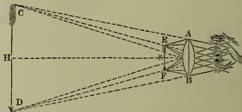
In fig. 1 AB is a double convex lens, in front of which, between it and its focus, K, but near that focus, we have drawn an arrow, EF, to represent the object under inspection. The cones drawn from its extreme points are representative rays of light, diverging from these points and falling on the lens. These rays, if not interrupted in their course by the lens, AB, would be too divergent for the eye to bring them to a focus upon the retina (see EYE). But after traversing the lens, AB, they travel, if the object be sufficiently near the focus, K, in lines which are nearly parallel, or which apparently diverge from points, such as C, D, not nearer to the eye than the least distance of distinct vision, which is, for most individuals, about ten inches. Suppose the lens is as close as may be to the eye, and that the object, EF, is brought up to it to such a distance that the virtual image, CD, is at 10 inches' distance from the eye; and let us further suppose that the focal length of the lens is such (see LENS) that the image, CD, is ten times, linearly, as great as EF; then the eye, instead of vainly striving to see the small object, EF, near K, will seem to perceive distinctly an image ten times as great linearly, and situated at the convenient distance, H. The magnification of the lens is independent of the eye, and is the relation between the size of the image and that of the object. When one of these is at an infinite distance and the other at a principal focus, the magnifying power depends on the position of the eye, and is the ratio between the apparent size of the object at any given distance and that of the virtual image as seen with the aid of the lens; this may be seen to increase as the eye is withdrawn to a greater distance, especially when the one eye is used to look at the object, say a page of print, and the other to look through the lens; but the greatest retinal image is formed when the lens is close to the eye.
We have supposed the whole of the light to enter the eye through the lens, AB (fig. 1); but so large a pencil of light passing through a single lens would be so much distorted by its spherical figure, and by the chromatic dispersion of the glass, as to produce a very indistinct and imperfect image. This is partly rectified by applying a stop to the lens, so as to allow only the central portion of the pencil to pass. But, while such a limited pencil would represent correctly the form and colour of the object, so small a pencil of light is generally unable to illuminate the whole of the magnified picture with any adequate degree of brilliancy, and is therefore incapable of displaying those organic markings on animals or plants which are often of so much importance in distinguishing one class of objects from another. Dr Wollaston was the first to overcome this difficulty, which he achieved by constructing a doublet (fig. 2), which consists of two plano-convex lenses, having their focal lengths in the proportion of 1 to 3, and placed at a distance best ascertained by experiment. Their plane sides are placed towards the object, and the lens of shortest focal length next the object. By this arrangement the distortion caused by the first lens is corrected by the second, and a well-defined and illuminated image is seen. Dr Wollaston's doublet was further improved by Mr Holland, who substituted two leuses for the first in Dr Wollaston's doublet, and retained the stop between them and the third. This combination, though generally called a triplet, is virtually a doublet, inasmuch as the two lenses only accomplish what the anterior lens did, although with less precision, in Dr Wollaston's doublet. In this combination (fig. 3) of
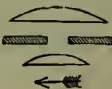
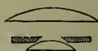
lenses the errors are still further reduced by the close approximation of the lenses to the object, which causes the refraction to take place near the axis, and thus we have a still larger pencil of light transmitted, and have also a more distinct and vivid image presented to the eye.
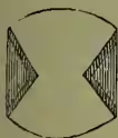
Simple Microscope.—By this term we mean an instrument by means of which we view the object through the lens directly. These instruments may be divided into two classes—those simply used in the hand, and those provided with a stand or frame, so arranged as to be capable of being adjusted by means of a screw to the exact focal distance, and of being moved over different parts of the object. The single lens used may be either a bi-convex or a plano-convex. When a higher power is wanted a doublet, such as we have already described, may be employed, or a Coddington lens, which consists (fig. 4) of a sphere in which a groove is cut and filled up with opaque matter. This is perhaps the most convenient hand lens, as it matters little, from its spherical form, in what position it is held. In the simple microscope single or combined lenses may be employed, varying from a quarter to two inches. There are many different kinds of stands for simple microscopes made, but, as they are principally used for dissection, the most important point next to good glasses is to secure a firm, large stage for supporting the objects under examination. When low powers alone are used the stage-movements may be dispensed with; but when the doublet or triplet is employed some more delicate adjustment than that of the hand is necessary.
Compound Microscope.—In the compound microscope in its simplest form the observer does not view the object directly, but an inverted real image or picture of the object is formed by one lens or set of lenses, and that image is looked at through another lens. The compound microscope consists of two lenses, an object and an eye lens; but each of these may be compounded of several lenses playing the part of one, as in the simple microscope. The eye-lens, or ocular, is that placed next the eye, and the object-lens, or objective, that next the object. The objective is generally made of two or three achromatic lenses, while the eye-piece generally consists of two plano-convex lenses, with their flat faces next the eye, and separated at half the sum of their focal lengths, with a diaphragm or stop between them. Lenses of high power are so small as to admit only a very small beam of light, and consequently what is gained in magnifying power is often worthless from deficient illumination. Various devices have been employed to overcome this difficulty. The light may be concentrated by achromatic condensers placed beneath the stage, or the curvature of the lens may be such as to allow as large a number of divergent rays as possible to impinge upon it. Such a lens is said to have a large 'angle of aperture,' the angle of aperture being that made by two lines converging from the margins of the lens to its focal point. Recently lenses, termed 'immersion lenses,' have been constructed, of such a curvature that when immersed in a drop of liquid placed over the object light is admitted on all sides. With an immersion lens there is high magnifying power with sufficient illumination.
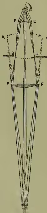
The accompanying diagram (fig. 5) explains the manner in which the complete compound microscope acts. We have here represented the triple achromatic objective, consisting of three achromatic lenses combined in one tube, in connection with the eye-piece, which now consists of the field-glass, FF, in addition to the eye-glass, EE. The function of the field-glass, FF, is that the rays of light from the object tend, after traversing the objective, to form an image at AA; but coming in contact with the field-glass, FF, they are bent, and made to converge at BB, where a real image is formed, at which place a stop or diaphragm is placed to intercept all light, except what is required to form a distinct image. From BB the rays proceed to the eye-glass, EE, exactly as they do in the simple microscope. The real image formed at BB is therefore viewed as an original object through the eye-glass, EE. The lens, FF, is not essential to a compound microscope; but as it is quite evident that the rays proceeding to AA would fall exterior to the eye-lens, EE, if it were removed, and only a part of the object would thus be brought under view, it is always made use of in the compound microscope.
A mirror is placed under the stage for reflecting the light through the object under observation. This method of illumination by transmitted light is used when the object is transparent. When opaque, light is reflected on the object by a bull's-eye lens, called a condenser. The best instruments are supplied with six or seven object-glasses, varying in magnifying power from 20 to 2500 diameters. The eye-pieces supplied are three in number, each of which consists of two plano-convex lenses, between which a stop or diaphragm is placed, half-way between the two lenses. As the magnifying power of a compound microscope depends on the product of the magnifying powers of the object-glass and the eye-piece, it follows that its power may be increased or diminished by a change in either or both of these glasses. In the mechanical arrangements it is of importance to have the instrument so constructed that, while every facility is afforded for observation and easy adjustment, there should also be great steadiness. These ends are achieved in various ways, of which fig. 6 is one of the simplest: a, brass stand, supported on three feet; b, mirror supported on trunnions; c, diaphragm, pierced with circular holes of various sizes, to regulate the admission to the object of reflected light from the mirror; d, stage-plate, on which the object is placed; e, screw, with milled head for fine adjustment; f, the object-glass or objective; g, brass tube in which the body of the instrument is moved,
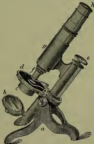
so as to effect the coarse adjustment; , the eye-piece, or ocular.
For a more complete account of the different kinds of microscopes, and the various purposes to which they are applied, see Quekett On the Microscope (1885); Carpenter, The Microscope (1862; 6th ed. 1880); works on the microscope by Hogg and Beale; The Microscopist, by Wythe (3d ed. 1877).