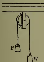
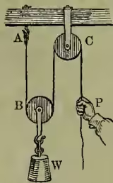
Pulley, one of the mechanical powers, consists of a wheel, with a groove cut all round its circumference, and movable on an axis; the wheel, which is commonly called a sheave, is often placed inside a hollow oblong mass of wood called a block, and by the sides of this block the extremities of the axle of the sheave are supported; the cord which passes over the circumference of the sheave is called the tackle. Pulleys may be used either singly or in combination; in the former case they are either fixed or movable. The fixed pulley (fig. 1) gives no mechanical advantage; it merely changes the direction in which a force would naturally be applied to one more convenient; thus, W can be raised without lifting it directly by merely pulling P down. The single movable pulley, with parallel cords, gives a mechanical advantage = 2 (fig. 2); for a little consideration will show that, as the weight, W, is supported by two strings, the stress on each string is , and the stress on the one being supported by the hook, A, the power, P, requires merely to support the stress on the other string, which passes round C. The fixed pulley, C, is only of service in changing the naturally upward direction of the power into a downward one. If the strings in the single movable pulley are not parallel there is a diminution of mechanical advantage—i.e. P must be more than half of W to produce an exact counterpoise; if the angle made by the strings AB and BC is 120°, P must be equal to W; and if the angle be greater than this there is a mechanical disadvantage, or P must be greater than W. The following are examples of different combinations of pulleys, generally known as the first, second, and third systems of pulleys. In the first system one end of each cord descends to a fixed support above; each cord descends, passes round a pulley (to the lowest of which the weight, W, is fastened), and is fastened to the block of the next pulley, with the exception of the last cord, which passes round a fixed pulley above, and is attached to the counterpoise, P. The tension of a string being the same in all its parts, the tension of every part of the string marked (1) in fig. 3 is that which is produced by the weight of P; consequently, as the last movable pulley is supported on both sides by a string having a tension, P, the tension applied in its support is 2P. The tension of the string marked (2)
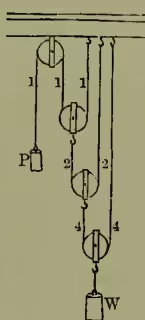
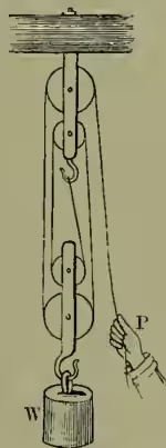
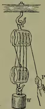
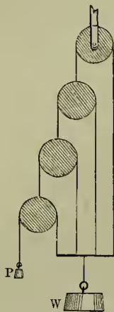
is therefore 2P, and the second movable pulley is supported by a force equal to 4P. It may similarly be shown that the force applied by the strings marked (4) in support of the last pulley (which is attached to W) is 8P. Hence we see that, according to this arrangement, 1 lb. can support 4 lb. if two movable pulleys are used; 8 lb. if there are three movable pulleys; 16 lb. if there are four movable pulleys; and if there are movable pulleys 1 lb. can support lb. It must be noticed, however, that in practice the weight of the cords, and of the pulleys, and the friction of the cord on the pulleys must be allowed for; and the fact that in this system all of these resist the action of the power, P, and that to a large extent, has rendered it of little use in practice.—The second system is much inferior in producing a mechanical advantage, but it is found to be much more convenient in practice, and is modified according to the purpose for which it is to be used; two prevalent forms are given in figs. 4 and 5. In this system one string passes round all the pulleys, and, as the tension in every part of it is that produced by the weight of P, the whole force applied to elevate the lower block with its attached weight, W, is the weight P multiplied by the number of strings attached to the lower block; in fig. 4 , and in fig. 5 , the pulleys in the upper block being only of use in changing the direction of the pulling force. This system is the one in common use in architecture, in dock-yards, and on board ship, and various modifications of it—such as White's pulley, Smeaton's pulley, &c.—have been introduced; but the simpler forms shown above have been found to answer best.—The third system (fig. 6) is merely the first system inverted, and it is a little more powerful, besides having the weight of the pulleys to support the power, instead of acting in opposition to it, as in the former case.—The mechanical advantage can be traced out by finding from the form of the combination the ratio between the run of the tackle over the last sheave and the vertical ascent of W, when motion is set up. Theoretically, the larger the number of movable pulleys in any one combination the greater is the mechanical advantage afforded by it; but the enormous friction produced, and the want of perfect flexibility in the ropes, prevent any great increase in the number of pulleys.