Pumps, machines for lifting liquids to a higher level, include (1) the Lift or Suction Pump, (2) the Lift and Force Pump, (3) the Pulsometer, (4) the Chain-pump, (5) Spiral Pumps, (6) the Centrifugal Pump, (7) the Jet-pump, (8) the Persian Wheel, (9) Scoop-wheels.
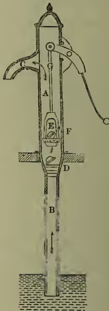
(1) The Lift or Suction Pump (fig. 1).—A is the cylinder (the 'barrel'), closed or open at the top; B is a pipe (the 'suction-pipe') communicating with the water to be raised; C is a 'discharge-pipe,' which may be reduced to a mere spout; D is a valve, opening upwards only; E is another valve, also opening upwards only, and borne by F; F is the 'bucket,' a hollow cylindrical piece of wood or metal which is made, by leather or by hemp or other packing, to fit the barrel just so closely that water cannot travel between the bucket and the barrel; G is the piston-rod, driven by hand, steam, windmill, or animal power, and moving the bucket up and down in the barrel. Each upward stroke of the piston at first lifts air, of which none can travel back past the bucket; a partial vacuum is produced in B; water ascends in B until the external atmospheric pressure is balanced by the partial atmospheric pressure below D plus the weight of the water column in B; as F now descends, air gets to the upper side of the valve, and is lifted on the upstroke, and so on; so that, if the valve D be not more than at most 33 feet above the water below (in practice 25 feet or less), water will be, step by step, pushed up B by the external atmospheric pressure until the valve D is under water; thereafter the succeeding strokes of the pump operate on the water above D and force it into the discharge-pipe, C, the external atmospheric pressure keeping the space below D filled with water. The power expended is applied (1) in lifting water; (2) in overcoming the pump-friction; (3) in overcoming the water-friction; and, (4) where the pump is ill-shaped, in producing eddies and broken water. A lift-pump must be very carefully proportioned and constructed in order to utilise, in water-lifting, one-half of the whole power expended in working it. Such pumps must work slowly, so that the valves may close properly; and an air-vessel is, if C be not a mere spout, required on C so as to minimise shock and render the outflow less intermittent, by the compression and elastic expansion of the air contained in it. The outflow is also regulated by driving two or three pumps off the same shaft and properly timing their relative motions.
(2) The Lift and Force Pump (fig. 2).—The piston is solid, and the valve E, instead of being carried by the piston, is fitted in the discharge-pipe. During the downward motion of the piston water is forced past the valve E; it cannot return;
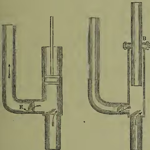
Fig. 3.
and water may thus be forced to considerable heights. Sometimes (fig. 3) the piston is made to fit, not the barrel, but the stuffing-box, B, which can be tightened down on it so as to make the fit good. An air-vessel, or a loaded hydraulic press called an 'accumulator,' is fitted on the discharge-pipe so as to minimise shock and intermittence; and double pumps are very generally employed, either directly driven by steam-engine pistons or driven by a flywheel. Force-pumps are used for deep wells and mines, hydraulic presses, boiler feeds, creasing timber, hydraulic lifts, steam fire-engines both land and marine, and hydraulic power supply.
(3) The Pulsometer.—Two chambers, A and B, converge above and communicate with a single steam-pipe; a ball-valve shuts off either A or B, but not both at the same time, from the steam; A and B each have a discharge outlet and a suction inlet, both these having valves. The whole is filled with water; the steam drives water from, say, A into the discharge-pipe: condensation takes place and the ball-valve is pulled over, so as to shut off the steam from A: the steam then acts in B in the same way as it had done in A, while in the meantime A, where there is a partial vacuum, is being filled with water from the suction-pipe. The two chambers thus act alternately. The whole contrivance can be hung by chains and let down to the required position; and it is greatly in use in contractors' work.
(4) The Chain-pump.—This pump is formed of plates called lifts or buckets, fastened, now generally by their centres, to an endless chain and moving upwards, in a case or 'barrel' which is in places constricted so as just to let the buckets pass. Chain-pumps are noisy and somewhat apt to break down; but they can lift very gritty or muddy material. Dredging-machines (q.v.) with their buckets are a variety of this device.
(5) Spiral Pumps.—An Archimedes' Screw (q.v.) is rotated round its axis so as to make water slip up the inclined plane of the screw. They are very economical in power, and they work so regularly that they act as meters.
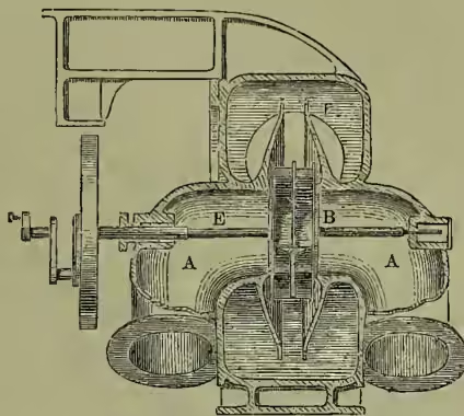
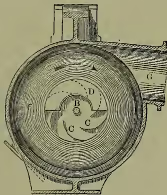
(6) Centrifugal Pumps (figs. 4 and 5).—The water enters by the supply-pipes, A, A, which lead to the central orifices of the fan, B, B; it then traverses the passages, C, C, formed by the vanes and the side covering-plates, D, of the fan. The fan is made to rotate from the shaft, E. The water acquires a rotatory motion while passing through the passages of the rotating fan; it then enters the whirlpool-chamber, F, and is discharged by the pipe, G, at the circumference of F; and the velocity of rotation of the fan determines the height to which the water will rise in the discharge-pipe. This velocity cannot conveniently be made to exceed a certain limit; hence the utility of centrifugal pumps is practically limited to low lifts; but as they can be made very large they can deal with enormous quantities of water; and they are much used for pumping in docks, canals, marsh and polder draining, land-reclaiming, and the like. As they have no valves they are little liable to become choked. In nearly all modern centrifugal pumps the whirlpool-chamber, F, the purpose of which was to reduce the ultimate velocity of outflow and correspondingly to increase the pressure, is dispensed with; and the same end is attained without wasting energy through friction in the vortex, F, by shaping the vanes of the fan so as to reduce the velocity. See Cotterill's Applied Mechanics.
(7) The Jet-pump, now not much used, is practically a Giffard's Injector (q.v.) worked by water from a height instead of by steam.
(8) The Persian Wheel.—An under-shot wheel (mill-wheel in which the water flows under the wheel) in which little buckets are carried by the rim of the wheel so as to pick up water from the stream and deliver it at the top of the wheel.
(9) Scoop-wheels or flash wheels: equivalent to breast water-wheels with reversed action; driven by windmills or by steam, they raise water in their buckets and deliver it a few feet higher up; in some cases they have curved blades, and the water is delivered at the centre of the wheel.
See Pumps and Pumping Machinery, by Frederick Colyer, C.E. (Lond. 1886); also see AIR-PUMP.