Sextant, an instrument for measuring the angular distance of objects by means of reflection. The principle of its construction depends upon the theorem that, if a ray of light suffer double reflection, the angle between the original ray and its direction after the second reflection is double of the angle made by the reflecting surfaces. Thus, let A and B (fig. 1) be two mirrors perpendicular to the same plane, and inclined to each other, and let SA be a ray of light, which falling upon A is reflected on B, and re-reflected in the direction BC, then
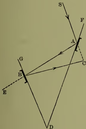
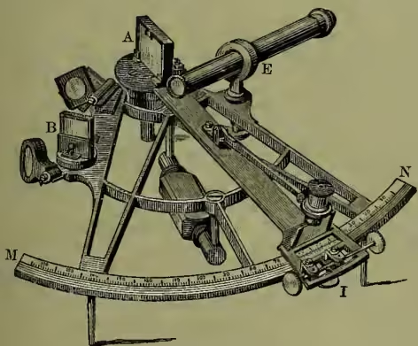
ACB is the angle between the original and finally reflected rays, and ADB is the angle between the mirrors. Now, as the angle of reflection is equal to the angle of incidence, , and ; but ; and also ; therefore , which proves the truth of the theorem. The instrument of which this theorem is the principle is a brass sector of a circle in outline; the sector being the sixth part of a complete circle, for which reason the instrument is called a sextant. Fig. 2 shows the essentials of its construction; AMN is the sector whose curved side, MIN, is the sixth part of a circle; A is one mirror wholly silvered, placed perpendicular to the plane of the sector, and on, and in line with, the limb AI, which is movable round a joint at or near A; B is the other mirror, also perpendicular to the plane of the instrument, and silvered on the lower half only, the upper half being transparent; E is an eyete-hole or small telescope. The graduation runs from N to M (on a slip of silver, platinum, or gold let into the rim), and is so adjusted that, when the movable limb is drawn towards N till the mirrors A and B are parallel, the index which is carried at the foot of the movable limb is opposite zero on the graduation. If we suppose that this zero-point is at N, it is evident that the angle between the mirrors is equal to the angle NAI; and again, if instead of graduating from at N to at M, which is the proper graduation for the sixth part of a circle, the graduation be made from to —i.e. each half degree being marked as a degree, and similarly of its aliquot parts—then the angle NAI, read off by the index at I, will show at once the angle between the incident and finally reflected rays. The mode of using the sextant consists in placing the eye to the telescope or eyete-hole, and observing one object directly through the unsilvered part of B, and then moving the index till the image of the other object, reflected from A upon the silvered part of B, coincides with or is opposite to the first object; then the angle, read off at I, gives the angle between the objects. For additional accuracy a vernier is attached to the foot of the movable limb.
The sextant is capable of very general application, but its chief use is on board ship to observe the altitude of the sun, the lunar distances, &c., in order to determine the latitude and longitude. For this purpose it is necessary to have stained glasses interposed between the mirrors A and B, to reduce the sun's brightness. These glasses (generally three in number) are hinged on the side AM, so that they may be interposed or not at pleasure. B is the glass through which the horizon is perceived, and has hence received the name of the horizon-glass; while the other mirror, from its being attached to the index-limb, is called the index-glass.
The sextant is liable to three chief errors of adjustment: 1° if the index-glass be not perpendicular to the plane of the instrument; 2° if the horizon-glass be not perpendicular to the plane of the instrument; and 3° if, when the mirrors are parallel (which is the case when a very distant body, such as the sun or moon, is observed directly through B, and found to coincide with its image in the lower part of B), the index does not point accurately to ; this last is called the index-error, and is either allowed for, or is remedied by means of a screw, which moves the index in the limb AI, the latter being stationary. The first two errors are also frequently remedied by means of screws working against a spring, but in the best instruments the maker himself fixes the glasses in their proper position.—The quadrant differs from the sextant only in having its arc the fourth part of a circle, and being consequently graduated from to ; the octant contains , and is graduated from to ; while the repeating-circle, which is a complete circle, is graduated from to . A common form of the sextant is the 'snuff-box' sextant, which is circular in shape, and, as it can be conveniently carried in the pocket, is the form most frequently used by land-surveyors.
The idea of a reflecting instrument, on the principle of the sextant, was first given by Hooke about 1666; but the first instrument deserving the name was invented by John Hadley (q.v.) early in the summer of 1730, and a second, and much improved form of it, was made by him a short time afterwards. Halley, at a meeting of the Royal Society, claimed for Newton the priority of invention, and in October 1730 a Philadelphian, named Godfrey, also asserted his claim as the original inventor; but that learned body decided that Newton's claim was unsupported by even probable evidence, and that Hadley's and Godfrey's inventions were both original, but that the second form (which is almost the same as the common sextant now employed) of Hadley's instrument was far superior to his first form and to Godfrey's. See works by H. W. Clarke (1885) and C. W. Thompson (1887).