Telegraph (Gr. tēle, 'far off,' and graphō, 'I write'). This is a general name for any means of conveying intelligence other than by voice or by the transmission of written messages. Perhaps also the idea of speed is generally understood. Alarm fires (see BEACON), the Semaphore (q.v.), and Signalling (q.v.) as used at sea are among the earlier forms of telegraphy, but now all such agents are thrown into the shade by the electric telegraph.
The idea of telegraphic communication by means of magnets is certainly more than two and a half centuries old. In 1632 Galileo, the great astronomer, referred to a secret art by which, through the sympathy of magnetic needles, it would be possible to converse at great distances. Again, in 1753, when a more defined idea of electricity had begun to dawn, a letter appeared in the Scots Magazine signed 'C. M.' (now almost certainly recognised to be Charles Morrison, a native of Greenock, who practised as a surgeon at Renfrew, from whence the letter was dated), in which 'an expeditious method of conveying intelligence' from one place to another by means of electric power was so clearly set down that we cannot but recognise that the writer must have had a considerable appreciation of the possibilities of electric communication. Many quiet workers occupied this field of research from that time until 1837, which is the generally recognised year of the birth of the electric telegraph. Limited space forbids anything but a passing reference to the work of the fathers of the telegraph. If a comparison may be made, we may say that what Wheatstone and Cooke were in the Old World, Morse and Alfred Vail were in the New. The claim that may justly be made for the recognition of the genius of either workers does not in the least militate against the recognition of that of the others; but it must be conceded that while the method originated by the English inventors has found acceptance principally in England, the Morse system is of world-wide use, and has supplanted the other even in England except for railway working, for which the needle system is most admirably suited. We must now proceed to furnish such information as will give some idea of the present state of the
Copyright 1892 in U.S.
by J. B. Lippincott
Company. science, with some notice of the more important systems in use in Britain, together with a few general statistics. In doing this it will be necessary to assume on the part of the reader some general knowledge of the chief features of Electricity (q.v.; and see also MAGNETISM).
The general subjects dealt with occur in the following order, and it may be noted that special terms have been included and explained as far as possible. I. Construction—(1) lines, overhead and underground; (2) poles and insulators; (3) wire; (4) earths and earth-currents; (5) circuit; (6) batteries—universal battery. II. Apparatus—(1) needle system and Morse code; (2) the sounder system; (3) the Morse recorder; (4) the relay, polarised and non-polarised; (5) the double-current system; (6) type-printing instruments—Hughes's, &c.; (7) the duplex system; (8) the quadruplex system; (9) multiplex telegraphy; (10) automatic telegraphy; (11) 'news' circuits; (12) repeaters; (13) submarine telegraphy—cables. III. Statistics.
I. Construction.—(1) Telegraph lines may be either overhead or underground. There can never be any question when the choice is open as to the adoption of the overhead system, as not only is the first cost less, but it is better for working purposes, and faults can be easily traced and removed. On the other hand, climatic conditions do not affect underground lines, while a severe storm will sometimes do so much damage to open work as to cripple the whole system. Nearly all the wires in large towns are necessarily underground, as there are many serious objections to overhouse lines. For instance, there are more than 2600 wires led into the Central Telegraph Office in London which are almost without exception underground.
(2) Poles and Insulators.—Overhead wires are supported for the most part upon creasoted wooden poles by means of insulators. No hard and fast rule can be given as to the number of poles that should be used. For minor lines twenty or twenty-two may be used, but on main lines the number should be between twenty-six and thirty to the mile. Ordinarily the lowest wire on a pole should be not less than 12 feet from the ground, so that, allowing for setting in the ground (which varies from 4 feet to 6 for ordinary poles), and the sag or dip of the wire between the poles, the length of the poles used on branch lines is usually about 20 or 22 feet, and this is increased by 1 foot for each two additional wires required. The object of the insulator is to isolate the wire from any material which would be liable to conduct the current from the wire, and the material of which the insulator is made is therefore of much importance. Glass is a material which possesses some of the necessary qualifications in a high degree, but its extreme readiness to condense moisture, whereby it becomes coated with a conducting film, is fatal to its employment. Ebonite also fails in practice, and brown earthenware is almost the only substance that has hitherto been able to stand out as a competitor with porcelain. This latter is distinctly the best material to use, but earthenware has the advantage as regards price. Cordeaux's screw insulator is constructed simply to screw on the bolt so that it can be easily renewed or removed. When insulators are very subject to breakage by stone-throwing they are protected by an iron cap.
(3) Wire.—The wire used is either galvanised iron-wire (i.e. iron-wire coated with zinc) or, for special purposes, hard drawn copper-wire. Underground wires are laid in cast-iron pipes provided with flush boxes at intervals which provide means of getting at the wires at intermediate points for testing, tracing faults, &c. These wires are of copper coated with gutta-percha. A 3-inch pipe will take as many as eighty wires.
(4) Earths.—In 1838 Steinheil discovered that, if a good electrical connection is made with the ground at each end of a single line, the earth will act as a substitute for a return wire. This was a very important discovery, for not only does it save the expense of a return wire, but it also reduces the resistance of the line by nearly half, with several attendant advantages. The technical expression 'earth' is applied to this connection, and an 'earth' may consist simply of a wire attached to a metal plate of a large surface buried in soil that is sure to be always damp; but metal pumps, or better still the iron water-pipe system in towns, will generally form excellent earths. Iron gas-pipes will do very well in default of water-pipes, but on no account must lead gas-pipes be used, as there is a possibility of a discharge of lightning fusing the pipe and causing an explosion or a fire by igniting the gas. Earth-currents.—From causes as yet unexplained different parts of the earth are frequently at different potentials, so that, if two such points be connected by a wire joined to earth at each end, it is traversed by an earth-current. Such currents vary during different periods of every day, and at certain periods they acquire such strength as to be termed 'electric storms.' They then may often render ordinary working impossible, and on long cable circuits may even endanger the safety of the cable. In order to secure communication in such circumstances it suffices, where practicable, to use a return wire instead of earth. Lines whose terminations run north-east and south-west are most liable to interruption.
(5) Circuit.—This term, which is of very frequent use, implies the whole path along which a current of electricity may be supposed to flow; that is, for instance, the battery, lever of key, line-wire, coils of receiving apparatus, and the 'earth' at each end. Short-circuit implies that the circuit between two particular points (say the two ends of a coil of wire) is bridged across by a conductor of no resistance.
(6) Batteries.—The batteries most commonly used for telegraph purposes are bichromate, several forms of Daniell's, and two or three forms of Leclanché, but latterly secondary batteries have been introduced with great success. Ordinarily each set of apparatus at an office has a separate battery, but by a well recognised law of electricity the universal battery system is often applied where several circuits of much the same resistance terminate in one office. This means that several sets of instruments (usually not more than five) are joined up to a common battery, each of course working independently. The battery in this case necessarily wants more frequent renewal, but the first cost is less, and there is also a material saving in space, which is of very great importance in such cases—for instance, as at the Central Telegraph Office in London, where there are nearly 24,000 cells in use.
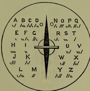
II. Apparatus.—(1) The Needle System.—In the earliest form of telegraph instrument, devised by Cooke and Wheatstone, five needles were used, each worked by two wires; this number was subsequently reduced to two, and now a single needle only is employed. Fig. 1 shows the dial of such an instrument. The needle normally hangs vertically, and is capable of motion to the right and left between two stops. The signals are formed by combinations of the two directions of deflection. The alphabet in general use, which is shown above on the face of the dial, is due to Professor Morse, and is hence called the 'Morse Code.' The letters most frequently used—e and t—are represented respectively by a deflection to the left and to the right. All the other letters of the alphabet are formed by two, three, or four combinations—the length of the signal for each letter being arranged with approximate reference to the frequency of its occurrence in ordinary English writing. In the same way the numerals, stops, and other signals are formed. The figures are represented by five signals, thus :
| (1) . — — — — | (6) — . . . . |
| (2) . . — — — | (7) — — . . . |
| (3) . . . — — | (8) — — — . . |
| (4) . . . . — | (9) — — — — . |
| (5) . . . . . | (0) — — — — — |
and the stops, &c. by six combinations. The dots and dashes represent respectively deflections to the left and right. Figures, however, are always spelt in full on the single needle. The needle system is specially English, and is used almost universally for railway telegraphs throughout the three kingdoms. It has no equal for working a large number of offices on one circuit, and it has the great advantage of being extremely easy to learn and simple to work.
(2) The Sounder System.—For commercial telegraphy, however, the sounder system is distinctly the most generally serviceable of hand-worked systems. Opposite the poles of an electro-magnet is placed a soft-iron cross-piece or armature, fixed upon a lever which is so pivoted that a spiral spring attached to the end of one arm tends to hold the armature away from the poles of the magnet. The passing of a current through the coils causes the armature to be attracted, and its motion is limited by two adjustable screws which are so arranged that the two sounds emitted when the end of the lever strikes upon them are easily distinguishable. Sound-reading then consists really of noticing the intervals of silence between these two sounds. The Morse code as shown above is used, and (1) a dot is represented by a very short interval of silence between the downward stroke and the upward stroke of the armature lever; (2) a dash is represented by an interval three times as long; and in the same way the space between (3) the elements of a letter; (4) the letters of a word; and (5) the words of a sentence are represented by intervals between the downward and the upward strokes respectively equal to one, three, and five dots. The instrument by which these signals are spaced out at the sending station is called a key. A single current key consists simply of a lever so
Fig. 2.
pivoted as to make electrical contact with one or two stops. This is shown diagrammatically at K in fig. 2, where B represents the battery and S the sounder. Normally a spring holds the lever of the key in the position shown, so that signals sent from the other stations pass from line to the lever of K, thence by way of the back stop through the sounder to earth. When, however, the handle of the lever is pressed a current passes from the battery, B, by way of the front stop and the lever of the key to the other stations. Thus the duration of the signals received at a distant station is determined by the periods during which K is depressed.
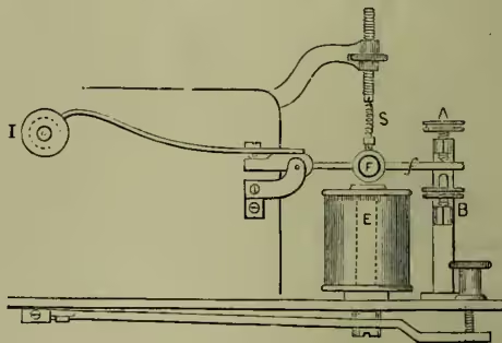
(3) The Morse.—It will be at once evident that a permanent record of the signals received may often be of considerable importance; hence, even before the introduction of the sounder, many devices for securing a permanent record were put forward. One of the earliest was the Morse Embosser, whose modern representative is known as the Writer or Inker. As shown in fig. 3, the combination of the electro-magnet, E, with the armature, F, fitted upon the lever, f, which is adjustable by the stops, A, B, and the spring, S, is virtually a sounder, the lever of which is prolonged beyond the pivot and fitted with a small disc, I, kept constantly rotating in a well of ink; above this inking disc a strip of paper is moved forward by clockwork, so that whenever the armature is attracted by the electro-magnet the disc makes ink-marks upon the paper of a length proportioned to the period of attraction. Thus the dots and dashes of the Morse code can be recorded.
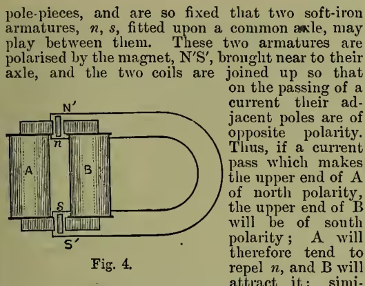
(4) The Relay.—For such instruments as the sounder and the ink-writer, however, where a comparatively considerable mechanical effect is required in order to secure satisfactory signals, a current must be used of such a strength as for a long line would absorb an inconveniently large amount of battery power. To obviate this a relay is introduced. A relay is practically a delicate form of the electro-magnet and lever of the sounder. The coils are wound with a finer and longer wire—finer only to get increased length of wire in the available space—and all its parts are proportioned with a view to the armature being actuated by very weak currents. The lever and limiting stops, which in this case are electrically insulated, are made to act as a key, and by this is introduced a local battery situated at the receiving station, and by means of which the sounder or other receiving instrument is actuated. The forms of relay are very numerous; but they may be divided into two groups—non-polarised, which are actuated alike by currents in either direction; and polarised, in which the armature, being either itself a magnet or permanently magnetised by a magnet placed in close proximity, is actuated according to the direction of the current. The form which is now most commonly used in England is the Post-office standard relay, the principle of which will be easily understood from fig. 4. Two coils, A and B, are fitted upon soft-iron cores having projecting larly (because the lower ends of A and B are then respectively south and north) s will be repelled from A and attracted towards B. All the forces therefore tend to move the armatures in the same direction, and so produce a very sensitive combination. The contact lever is fitted upon the axle with the armatures, and the contact stops are placed on either side.
(5) Double-current System.—The value of the polarised relay arises from its use in connection with the double-current system; the principle of which is so to arrange the key and the battery that during the time of transmission there is always a current passing to line, this current being in one direction when the key is up, and reversed when the key is depressed. Thus, with a polarised relay the 'spacing' current holds over the relay tongue to the spacing side, so that the spring or other power otherwise required for this purpose may be almost dispensed with; and consequently the relay will be actuated by a much less powerful 'marking' current than would be required for single-current working. In fact, double current expedites working, reduces the current required (and so tends to increase the working distance of a telegraph line), facilitates the intercommunication of several stations on a single circuit, and is a very important feature in an extensive system.
(6) Type-printing Instruments.—Many ingenious devices have been made in order to secure a record of messages sent not merely in a 'code,' but in plain printed characters. Fig. 5 is a fac-simile of a
PRINTING INSTRUMENT
Fig. 5.
piece of slip printed by means of the Hughes Type-printer. The action is principally mechanical, the electrical part being confined to the transmission and reception of a single current of short duration for each letter or other sign registered. The sending apparatus is like a piano keyboard with the letters and other signals engraved upon the keys; but the mechanism is so complex and so sensitive that only the most skilled operators can be entrusted with its working. It is not used in England except for circuits which are in communication with the continental systems. Other printing systems are in use by various private news agencies. They generally require a current for every step forward of the type-wheel—say twenty-six currents to repeat a given letter (although it is really more)—but many ingenious arrangements are made for them, including a device by Mr F. Higgins of the Exchange Telegraph Company which prints in column form instead of merely on a continuous slip.
(7) Duplex System.—The rapid increase in the business of telegraphy has called forth the exercise of the ingenuity of telegraph engineers to increase the capacity of a single wire for the transmission of messages. Duplex telegraphy is one way by which this has been effected. By this system messages can be sent on one line in both directions at the same time, thus practically doubling the carrying capacity of the wire, because station A can transmit a message to station B while B is sending another message to A. Under ordinary circumstances, when A is working to B on the open circuit principle, any interference on the part of B disconnects his receiving instrument, and so prevents A's signals from being recorded, because the back stop is disconnected (fig. 2). If now it can be arranged that the receiving instruments at both stations can be always in circuit, yet only affected by the currents sent from their own station when these currents interfere with the currents sent from the other station, then duplex telegraphy becomes possible. There are several modes of doing this, but we shall confine ourselves to a description of the differential method, which is almost exclusively that adopted in the British postal telegraphs.
If two circuits of precisely equal resistance be open to a current, it will divide itself equally between the two, and the currents in each wire will be exactly equal. If, for instance, the wire, (fig. 6), offer the same resistance as the wire, , the current in will have precisely the same strength as the current in . Now let an electro-magnet be similarly wound with two wires of equal length, one of which is in the circuit of , and the other in the circuit of . If the current through traverse the electro-magnet in the reverse direction to that through , it is evident that if the currents be equal the polarity induced by the one current must be exactly neutralised by that induced by the other current, for the effects are equal and opposite, and there will be no magnetism excited. Thus, as long as the two circuits are intact, the currents which flow will not affect the electro-magnet; but if the currents in be interrupted, those in will excite the electro-magnet, and if those in be interrupted, the currents in will excite the electro-magnet.
Assume A and B (fig. 7) to be two stations connected together by the line-wire, . Let E be an electro-magnet at A, wound as just described, K a key, and B a battery. Let represent resistance coils
Fig. 6.
Fig. 7.
or an artificial line, giving a resistance equal to the line circuit. Have a precisely similar arrangement at B, as shown. Now let us in the first place assume A alone to be working to B; every time the key, K, at A is depressed a current is sent from A's battery. This current divides at , the one half going through the wire in connection with in E, through , and at B, through the wire in connection with in E', through the key, K', to earth and thence back to the battery at A. This is called the line current. The other half, which is called the compensation current, passes around the electro-magnet, E, through the coil in connection with , through and back to the battery. As these two currents are equal, their effect on E is nil, but the line current passing through one coil only of E' operates it and causes signals to be given. Thus while A telegraphs to B its own instrument is not affected, but that at B is actuated. Similarly, when B alone is working to A its own instrument is not affected, but that at A is actuated. But when B is working to A at the same time that A is working to B, what happens? Every line current that leaves A at the same time that a line current leaves B is neutralised. The compensation current at A is now able to excite the electro-magnet, and the armature is moved in precisely the same way as if B's current were received. In the same way B's line currents are neutralised, and its compensation currents move the armature of E' in precisely the same way as if A's currents were received. Thus E and E' continue to be worked by their respective stations, regardless of the fact that the line currents are being continually neutralised, so that practically no current flows between A and B, and that they are operated sometimes by the line current and sometimes by the compensation current. Thus, while A sends messages to B, B can be sending messages to A upon the same wire and at the same time.
We assumed that the line current received at A from B was exactly equal to that proceeding from A to B, and that therefore they were exactly neutralised, but it is not so in practice, for owing to the effects of bad insulation the incoming line current is always weaker than the outgoing one. Hence the current received at A from B does not neutralise the whole of the current sent from A to B, but only a portion of it. It so weakens A's current to line that the compensation current preponderates over this resultant current, and the signals are registered by the preponderance. The difference in the strength of these two currents when both stations are working is very nearly equal to the strength of the current received at A when B alone works, so that the marks, whether made by the received line current or by the preponderating compensation current, are practically the same.
We have shown in the diagram that the same poles of the battery are to line, and that therefore the line currents flow in opposite directions; but the same effects occur if the opposite poles are to line, and the currents flow in the same direction. If the current from B flows in the same direction as that from A, the effect, when the two stations work simultaneously, is not to weaken the resultant current, but to strengthen it, and therefore to produce a preponderance of the current in wire over that in wire of relay E, and consequently to register signals; but in this case the marks made at A when both stations are working simultaneously are not made by the preponderance of the compensation current over the line current, but by the excess of the resultant line current over the compensation current.
There are certain irregularities in the working of such a system in actual practice which have to be provided against, due to variations in the resistance and in the electrostatic capacity of the line. Telegraph wires, in fact, are in a constant state of change. If A and B be connected together by an aerial wire supported at intervals of about 80 yards upon earthenware insulators, then the current which arrives at B from A must necessarily be less than that which leaves A, because at each pole a small portion of the current escapes or leaks to earth. No earthenware support is an absolute insulator. Moisture is deposited upon its surface. The amount of this moisture continually varies, and the resistance of the insulator to the leakage of the current varies with it. Hence the difference between the current leaving A and that arriving at B is constantly varying, and the effect upon the current leaving A is precisely the same as if the resistance of the line varied. If moisture be abundant more current leaves A, and the effect at the sending end is the same as if the resistance of the line-wire were reduced, but of course the increased current is not received at the other end. If the insulators become dry, less current leaves A, and the effect is the same as if the resistance of the line were increased. In fact, the resistance of the circuit does vary with the amount of moisture deposited on the insulators, and with the amount of dirt which necessarily adheres to them. Rain, fog, dew, and mist affect it. Lines exposed to the spray of the sea or the smoke of manufactures are peculiarly liable to this variation. Other causes also introduce irregularities which interfere with the constancy of a line. The wires are continually subject to accidents of various kinds, many of which tend to produce variable resistance.
Now what effect has this variation of the resistance of the line-wire upon duplex working, and how is it provided for? Clearly it disturbs the equality of the line and compensating currents, and causes the one to preponderate over the other; and if no means were adopted to compensate for this variation, duplex telegraphy would be impossible. Therefore the resistance in the compensation circuit is not made a fixed quantity, but consists of a series of resistance coils, by which the resistance of the compensation circuit can be varied in consonance with the variation of the line circuit. This instrument is called a Rheostat.
The compensation current is then adjusted by the aid of a differential galvanometer—i.e. a galvanometer double wound in the same way as the relay coils, the line current passing through one coil and the compensation current through the other in the opposite direction. Thus, when the compensation circuit is properly adjusted, the outgoing current will produce no effect upon the galvanometer.
Another modifying influence present on a telegraph line is electrostatic capacity—i.e., in brief, the power which it has of retaining or accumulating a portion of any current passing in it. This also has to be properly represented in the compensation circuit, and this is done by means of condensers. This is a term applied in electricity to an apparatus generally composed of alternate layers of tinfoil and paraffined paper (or mica), so arranged and connected as to form virtually a flat Leyden jar of large surface. As the capacity of a telegraph line varies with weather and from other causes, the condenser is also made variable.
It will be seen that satisfactory duplex working demands more skill and attention from the operators than does ordinary working; hence, as there are always times during which the requirements of business do not render it necessary that a circuit shall be worked duplex, and as it occasionally happens that owing to line variations, &c. duplex working becomes temporarily impracticable, all duplex circuits are fitted with switches, by means of which recourse may be had to ordinary working, still using the same apparatus.
(8) Quadruplex System.—Duplex telegraphy, as explained in the last section, means the transmission on the same wire of a message from (say) station A to station B while B is sending another message to A. If A or B be able to send two messages to the other at the same time on the same wire we have duplex telegraphy; and by combining these two systems—duplex and diplex—we may have four messages being sent simultaneously on a single wire, and this constitutes quadruplex telegraphy.
Suggested by Stark and Bosscha in 1855, it was not until 1874 that the problem of quadruplex working was solved by a device of Thomas Alva Edison, and the system now in use is the result of his efforts, supplemented by the work of Prescott, Gerritt Smith, and others. It may be broadly described as the duplex system provided with two keys in the sending circuit, and two relays, each having a coil in both the line and the compensation circuits (l and r, fig. 7). One key (on the A side of the set) is so connected that when its lever is depressed the battery connections are reversed, so reversing the direction of the current; while the other key (on the B side) is so constructed that the depression of the lever brings into circuit three times as much battery power, so that (whatever the direction of the current) it is increased in strength threefold. The A side relay at the other end responds correctly to the 'marking' and 'spacing' currents whatever their strength, while the relay on the B side is actuated only when the greater current is received, and then responds whether the current is 'positive' or 'negative.'
Since the introduction of the system into the Post-office telegraphs it has been considerably improved and simplified, so that now a battery having an electromotive force of 130 volts will satisfactorily work circuits that at one time required 200 volts, and even then worked indifferently. Among many varieties of useful arrangements of this system may be mentioned the 'forked' system, where, for instance, the London end of a circuit is fitted with full quadruplex apparatus, and the Leeds end is fitted with a special set, by means of which the A side of the London circuit is put in direct communication with Stockton, while the B side is connected to West Hartlepool. Both Stockton and West Hartlepool thus have direct duplex communication with London on a circuit common to both from Leeds. There are at present between thirty and forty wires worked on the quadruplex system in Great Britain.
(9) Multiplex Telegraphy.—In 1873 Meyer conceived the idea of so arranging two corresponding sets of apparatus at distant places that, by causing them to move in exact synchronism, the use of a telegraph line might be given successively to several operators for a very short period of time, so that one at each end would have it alone during the recurring periods. The synchronous movement of the two sets would ensure that each operator at one end should always have communication with the corresponding operator at the other.
Now that the idea has developed into a practical
Fig. 8.
system, it is known as the multiplex system. Fig. 8 indicates the principle. If the arms, a, b, which are electrically connected with the line-wire at A and B respectively, be made to rotate simultaneously around the circles 1, 2, 3, 4, making contact with the segments as they pass, then when a is on A 1 b will be on B 1, when a is on A 2 b will be on B 2, and so on. Again, if 1, 2, 3, 4 at each station be connected to a set of telegraphic apparatus (say a single-current sounder set), then each of the four sets at A will be successively connected with the corresponding set at B as the arms, a, b, move over the segments 1, 2, 3, 4. Thus for each revolution of the arms the instruments connected to A 1 and B 1 will be in direct communication once, and so also with A 2, B 2; A 3, B 3; and A 4, B 4.
Now suppose that each of the segments in fig. 8 be again divided into four and connected to each of the four sets of instruments instead of with only one of them (fig. 9). During one complete revolution of the arms each pair of instruments
Fig. 9.
will be in communication four times; and it is clear that if the arms in the two cases assumed be moving at the same rate, then, although the time during which each instrument is connected to line during one revolution of the arms will be the same, in the latter case it will be divided into four smaller periods, each separated by a period of disconnection of only one-quarter the length which occurs in the former case. This subdivision may of course be extended to a very considerable extent, and in practice it is so far extended that the intervals of disconnection are so short that with the apparatus used they may be neglected, so that each set of apparatus may be worked as if it and its corresponding set alone were connected to the line.
Meyer's system proving impracticable was improved upon by Baudot in 1881, but still without success, the difficulty being in maintaining synchronism. Paul La Cour of Copenhagen had in the meantime taken up the question of synchronism, and he invented a very ingenious plan which contained the germ of success. In 1882 Patrick B. Delany of New York perfected a plan for synchronism on La Cour's principle, and in 1884 produced a complete and workable multiplex system.
It will be seen that the principle of multiplex working differs so materially from the principle of duplex or quadruplex that all they really have in common is the capability of the simultaneous transmission of more than one message upon a wire. Hence the application of the same terms duplex, quadruplex, and sextuplex (working three messages each way on the quadruplex or similar principle) to the corresponding arrangements in multiplex working would tend to confusion, and therefore a special nomenclature, based upon the Greek word hodos, 'a way,' is adopted. Thus two-way working, that is, a mode of working by which two messages may be sent over the same line on this system, is known as diode; three-way, triode; four-way, tetrode; five-way, penthode; and six-way, hexode.
The great difficulty to be overcome in order to make the system practical was to secure the synchronous movement of the two arms rotating over the segments. The nearest approach to isochronism can be obtained with two tuning-forks pitched to absolutely the same note and set into vibration under exactly the same conditions, but the least interference (even a variation of temperature) is sufficient to affect the time vibration.
The instrument with the rotating arms and the segments is called the distributor, and its rotating arm is driven by means of a vibrating reed (virtually a tuning-fork) which intermittently completes the circuit of a battery through an electro-magnet in front of the poles of which an iron toothed wheel is fitted, this wheel being fixed upon the same axle as the arm. The reed, R (fig. 10), is simply a flat bar of mild steel firmly clamped at one end.
Fig. 10.
On one side of the free end is placed an electro-magnet, , the circuit of which includes the reed and a light contact spring. If the battery, B, be joined up as shown in fig. 10, the reed will be attracted towards the electro-magnet, and the circuit will thus be broken between the spring and the reed, attraction will therefore cease, and the reed will resume its original position. The circuit will then be again complete, and the same movement will be repeated, so that by this means the reed is maintained in vibration. The circuit of the battery, B, however, includes the coil of the electro-magnet, M, before the poles of which is pivoted the iron toothed wheel, W. When the circuit is complete and the cores of M are magnetised, the teeth of W are attracted to the position shown, but, as the attraction immediately ceases, the momentum that W has acquired is sufficient to carry it on, so bringing the next adjacent teeth within the range of attraction, when the circuit is again complete. Thus the reed is made to cause W to rotate. On tracing the course of the current from battery B it will be noticed that after passing through the electro-magnet, M, it has a course through , without passing through . This coil constitutes what is known as a shunt upon , and the current divides between the two in the inverse proportion of their resistance. The current cannot pass at C and , as C—a small condenser—is virtually a point of disconnection. The function of C and is to prevent sparking at the reed contacts from the discharge of the electro-magnet, M.
The motion of the wheel, W, is regulated by a fly-wheel placed over it; but, as a dead-weight would not accommodate itself to a sudden momentary variation of speed to which the motor may be subject, the fly-wheel consists of a wooden block in which are two deep concentric grooves which are filled with mercury. It is thus really the rings of mercury which form the fly-wheel, and they are not readily influenced by irregularity of running: even if the wheel be actually stopped the mercury continues to move, and will carry on the wheel if the period of stoppage be not too considerable.
In practice it at once becomes evident that the reed at one end of a line cannot possibly be expected to keep absolutely isochronous with that at the other, the result being that the signals sent from the set of segments 1 are received successively upon the receiving segments 1, 2, 3, &c. at the other end. In order to prevent this and keep 1 always to 1, 2 to 2, &c., sets of 'correcting segments' are provided. These are divided into 'sending' and 'receiving cor- rections,' and are so arranged that when the trailer on the arm, a, is upon a sending correction segment the trailer on b will be on a receiving correction segment, and vice versa; and if it should be lagging slightly behind its proper position the current will pass to a correcting relay, which will slightly quicken the slower reed. As these corrections can be applied if necessary nine times in each second, practical synchronism is secured.
The number of 'ways' which it is possible to work with this system is principally determined by the static capacity of the line, but a clear description of the theory of this is not possible here.
In actual working with the distributor used in England there are (practically) 162 segments, and 144 of these are grouped at intervals of twelve; so that they form twelve sets, apart from the correcting segments. The time of a complete revolution of the trailer at normal speed is one-third of a second, so that the time of contact with each segment is about th of a second, and each group is therefore connected to line for th of a second about thirty-six times per second. Special large relays, wound to a high resistance (1200 ohms) and connected with condensers of a large capacity, are used for receiving. By this arrangement the short impulses are converted into continuous signals, and thus the distributor (by connecting the line consecutively to certain pairs of sets of apparatus, one at each, end at very short intervals) enables each pair to work as well as if it alone had sole use of the line.
The maintenance of good working requires considerable skill and experience, as well as a thorough grasp of the whole principle, and it is necessary to make one station solely responsible for the adjustment of speed, &c.; otherwise the attempts of one station to secure good working may altogether upset similar efforts at the other end.
(10) Automatic Telegraphy.—The several kinds of apparatus already described are dependent entirely upon the hand for the transmission of the signals, and this necessarily limits the possible speed of transmission. Even the sounder—the fastest hand-worked instrument now used—cannot be worked by the most expert of operators at a rate exceeding forty-five words a minute. This is, however, by no means the limit of speed at which signals can be recorded even by the simple Morse inker; so that, although dependence upon the muscular motion of the wrist and the directive action of the mind may keep the speed at a comparatively low value, if the manipulation of the human agent can but be replaced by the precision and regularity of a suitably arranged machine, not only can we attain, but far exceed, the highest speed of the ordinary Morse or sounder. Hence early efforts were made to replace the hand-worked key by some mechanical contrivance which would not only remove the defects inherent to manual labour, but would secure precision in the formation of the characters, accuracy in the despatch of messages, and speed in transmission. Bain in the year 1846 was the first to propose this. He punched broad dots and dashes in paper ribbon, which was drawn with uniform velocity over a metal roller and beneath styles or brushes of wire, which thus replaced the key, for whenever a hole occurred a current was sent by the brushes coming in contact with the roller. The recording instrument was his chemical marker. The speed at which messages were transmitted at experimental trials was enormous; 400 messages per hour were easily sent; but when to the defects in the machinery were added the disturbances on the line from causes which were then unknown, it failed to commend itself. Perhaps the real reason for its not being persevered with was that at that time it was really not wanted; but now that telegraphic business has increased so enormously that extra wires are needed in every direction, apparatus which increases the capacity of the wires, by sending through them a greater number of messages in a given time, has become a necessity.
Wheatstone's system of automatic telegraphy is that which is used in England. Bain's method of punching has been considerably modified, and the messages are recorded on an exceedingly delicate form of direct ink-writer. The apparatus consists of three parts: the Perforator, by which the message is prepared by punching holes in a paper ribbon; the Transmitter, which sends the message under the control of the punched paper; and the Receiver, which records the message at the distant station when thus sent by the Transmitter.
The Perforator consists of three levers or keys the depression of which actuates five punches in a certain order, and also a groove and a feed arrangement to guide and move forward the paper as it is punched. The paper used is of a white description dipped in olive-oil. The three keys on being depressed drive the punches through the paper, cutting out clean round holes. The depression of the left-hand key causes the paper to be perforated with three holes in a vertical line thus: o ; the
depression of the centre key punches one—centre—
hole only, thus: o ; and the depression of the right-
hand key perforates four holes arranged thus: oo o
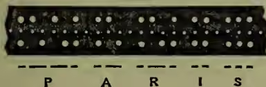
The left-hand key corresponds with dots, the centre with spaces, and the right-hand with dashes. It will be noticed that the holes made in the centre of the slip are smaller than those in the upper and lower rows. They admit the teeth of a little star wheel, which is turned through a small space whenever one of the keys is depressed, and which thus moves the paper forward a certain distance for each depression of either key by a species of rack and pinion movement. The space through which the paper is moved for a dash is twice the length of that through which it is moved by either of the other keys. In fact two central holes are punched for each dash required, and the star wheel is made to turn two teeth instead of one as in the case of the other two keys. If left, right, and centre be struck or depressed in succession, we have the paper prepared for the letter A; if right, left, left, left, and centre be depressed in succession, we have the paper prepared for the letter B; and so on for all the letters and signals. The word Paris thus prepared is indicated by fig. 11. An expert operator can punch at the rate of about forty-five words per minute, but the average rarely exceeds forty.
The Transmitter replaces the key of the ordinary apparatus, and it sends the currents by mechanical means under the control of the punched paper; hence the name of the system—the Automatic.
The arrangements of the parts is such that when running free the electrical portion sends alternate reverse currents of short duration, but when the slip is inserted these reversals are interrupted by means of the action of vibrating pins which tend to pass through the upper and lower holes of the slip.
Thus, to take the first letter of the slip shown above: the transmitter would be sending a spacing current when the back pin would rise through the first upper hole and permit a reverse (marking) current to be sent. On the next rising of the front pin it would pass through the first lower hole, and the reverse (spacing) current would pass. Thus a 'dot' would have been sent to line. The spacing current would remain on (for a period equal to the length of a dot) until the back pin again rose through the second upper hole, when the marking current would again be to line. When the front pin again rose its progress would be stopped by the slip, as there is no hole in the lower row beneath the second upper hole, and therefore no reversal would take place; the same applies also to the next rising of the back pin, and the marking current would therefore remain on until the occurrence of the second lower hole permitted a reversal; thus the second signal would be three times as long as the first—the proper respective lengths of a dot and a dash—and so on with the other signals and spaces.
The Receiver, by means of which the signals sent by the transmitter are recorded, is a direct ink-writer of a very sensitive character. The slip is drawn forward between two rollers by means of a train of wheels driven by a large weight. Before passing between the rollers the slip is brought near to a small inking disc which is rotated when the clockwork is in motion. The instrument is regulated by a fly to maintain uniform speed, and this fly is so arranged that by means of a lever the speed of slip can be adjusted to suit recording at any speed between 20 and 450 words per minute. The light marking disc is fixed to an axle geared with the clockwork, and rotates close to the periphery of a larger disc that moves, in the reverse direction, in a well of ink. This latter disc takes up the ink and feeds the marking disc by capillary attraction without introducing friction.
Passing now to the electrical arrangement of the receiver, the electro-magnets which work the recording armature consist of two bobbins of fine silk-covered copper-wire, having cores of carefully annealed soft iron. If these cores were provided with a cross-piece they would form what is generally known as a horseshoe-shaped electro-magnet; but less electro-magnetic inertia and greater rapidity of action are obtained by dispensing with the cross-piece and providing a second armature at the lower end of the axle, polarised in the opposite direction to the upper armature by means of the other pole of the inducing magnet. The arrangement is, in fact, similar to that shown by fig. 4. The working speed at present attained by this system is about 400 words per minute, although it has been possible to greatly exceed this speed in experimental running, and the workshop test is a speed of 450 words. An English telegraphic 'word' is taken to be twenty-four possible reversals on the transmitter.
(11) News Circuits.—Automatic instruments are employed on nearly all long circuits in England, not only because they increase the capacity of the wires for the conveyance of messages, but because they are so specially adapted for the conveyance of news, which is such a distinctive feature of the English system of telegraphy. One batch of news is often sent to a great many different places, and as four or even eight slips can be prepared at one operation, and one slip can be used several times, the labour of preparing for transmission is very much reduced. In fact, without this system it would be simply impossible to transmit the enormous amount of intelligence sent telegraphically all over the country. There are many news circuits radiating from the Central Telegraph Station, having three and four intermediate stations upon them, one or more of which 'repeat' or 'translate' onward to three or four more stations. Thus one punched slip disseminates the news to many places.
As already stated, the transmission of 'news' for the metropolitan and provincial press constitutes a special and distinctive feature of the English system. The work involved is enormous. During the year ending the 31st March 1891 5,003,409 press telegrams, containing no less than 600,409,000 words, were transmitted through the Postal Telegraph Department—an average of nearly two million words per diem. The press tariff, however, is arranged on so low a scale that the average price paid is only a little over 2d. per hundred words. During ten years the increase in news transmitted was about 83 per cent.; the numbers for the year ending 31st March 1881 having been 2,735,042 messages and 327,707,407 words. Messages can be sent at the press rate only after 6 P.M. To save delay and secure the transmission of their news at a fixed cost and without the inconvenience of keeping and checking telegraph accounts, several journals arrange for the sole use of a wire during certain hours of the evening. Thus, six Scottish journals appropriate nine London wires after 6 P.M.; four wires are allotted to as many Irish papers, while dailies published in English provincial towns absorb sixteen more. Some of the London dailies have a wire to Paris every evening, and one (the Daily News) also has one to Berlin.
Turning now to the news transmitted by the departmental operators, a large proportion is of general interest handed in by various news agencies. Such news items have to be sent to addresses in all parts of the country, and to effect this the slip once prepared can be used over and over again upon different circuits; moreover, by means of pneumatic power, the perforators at the Central Telegraph Office are capable of punching as many as four slips at a time, and, the pneumatic instruments being arranged to work two perforators, eight slips are thus prepared at one operation. Not only can one slip be used upon several different circuits, but often several offices which generally take the same class of news can be placed upon one circuit, so that all take the same messages simultaneously. On the other hand, in some cases when an address is outside the delivery of a news circuit the message has to be received, written up, and again transmitted. Indeed, in some cases this has to be done twice for some small towns which publish weekly or bi-weekly papers, and the second transmission may even have to be done by hand.
(12) Repeaters.—The length and description of a circuit has a great deal to do with the possible speed at which it can be worked. The greater the distance, as a rule, the lower the speed, and the reducing effect of a mile of underground wire is greater than 20 miles of aerial line. But even with an aerial line the leakage, &c. at the insulators makes the strength of current received, as compared with that sent out, proportionally less as the distance increases; and although it is of course possible to compensate for this loss by an increase of battery power, it is not so easy to compensate for the retardation due to electrostatic capacity. In dry climates the limit of distance for uninterrupted communication is rarely reached in practice, but in England the conditions are such that 400 miles may be taken as the limit. It then becomes necessary to take off the messages and repeat them by clerks, or to introduce a repeater or translator which, worked by the original currents, will automatically transmit or relay stronger currents similar in direction to, and of equal duration with, those which are passed through it. It is, in fact, an extension of the principle of the ordinary relay, and is introduced into the circuit for a similar reason—the relay is placed in circuit that it may be actuated by currents which would not work the sounder or Morse writer direct, and completes a local circuit in which the receiving apparatus is placed; the repeater is also arranged to relay similar currents to those which actuate it; but while the relay as ordinarily used is required to work an instrument in the same office, the prime function of the repeater is to retransmit the signals along an extension of the original line. By this means it is possible to work to any distance. Thus the Indo-European line from London to Telheran, a distance of 3800 miles, is worked directly (without any retransmission by hand) by means of five repeaters.
Varley introduced repeaters at Amsterdam to translate the English double-current system of working into the Continental single-current system in 1858, but in England the Post-office has introduced them to increase the rate of working. There is, however, a limit to the number of repeaters which can be employed on one line. The motion, friction, and inertia, both magnetic and mechanical, of the moving parts, and the introduction of disturbing electrical causes, prevent the duration of the contact of the tongue of the relay from being the exact counterpart of that of the sending key. It is of less duration. Retardation therefore takes place, and the rate of working is reduced with each relay added. In few cases in England is more than one repeater introduced, but by means of that an actual and decided increase of speed is obtained, due to the fact that the speed of working of the whole circuit is made that of its worst section alone. Their value may perhaps be best demonstrated by stating that by means of the Fast Duplex Repeater it is possible to mechanically retransmit messages, at the rate of 450 words per minute, simultaneously in both directions, on circuits exceeding 400 miles in length; and by referring to the fact that the highest speed attainable without repeater upon the London-Amsterdam wire is 116 as compared with a speed of 400 words with a repeater at Lowestoft, while the London-Dublin circuit without repeater will give only 120 words, and with a repeater at Nevin a possible 450. The latter figure, too, represents the highest possible speed not of the line but of the present form of instrument. It is impossible, however, in this article to give a correct idea of the working details of the repeaters now used.
(13) Submarine Telegraphy.—Owing to the retarding influence of a long submarine cable, by which it becomes difficult to pass ordinary electric currents through the cable except at very long intervals, giving the cable meanwhile time to discharge, and owing also to other disturbing causes, special means have to be adopted in working such cables in order to obtain the maximum possible speed. The method usually adopted was invented by C. F. Varley, and consists in interposing a condenser in the receiving circuit, so that instead of the circuit being complete it is interrupted at the condenser; and the instrument—a very sensitive form of galvanometer devised by Lord Kelvin (Sir William Thomson)—is actuated merely by the charge and discharge of the condenser. The Thomson galvanometer, without which long cables could scarcely have been commercially successful, consists essentially of a magnet composed of one or more pieces of watch-spring, -inch in length, cemented upon a small circular convex mirror of silvered glass, which is suspended by a short thread of cocoanut silk without torsion. This needle is suspended in the centre of a coil of very fine wire, and a ray of light is projected from a lamp upon the mirror. The beam of light is reflected at some distance upon a scale, and a very minute movement of the mirror therefore produces a considerable movement of the ray projected upon the scale. The movements of the spot of light upon the scale are read off in precisely the same way as the motions of the pointer on the dial of a single-needle instrument. The ordinary Morse system on an Atlantic cable could scarcely have a speed of one word a minute, while fifteen words is a usual speed with the reflecting galvanometer, and twenty-four have been obtained. Lord Kelvin also invented in 1867 the Syphon Recorder, by which cable messages can be permanently recorded as on the Morse system; this is now superseding the mirror instrument. For short cables, special applications of the ordinary systems are adopted.
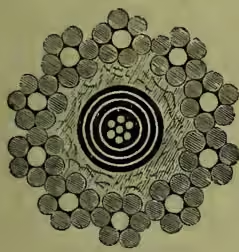
Submarine cables are generally made each on its own merits or according to the experience of the consulting electrician. The deep-sea portion of an
Atlantic cable laid in 1863, shown in fig. 12, was formed thus: Seven copper wires were laid up together, six being laid spirally around the seventh, and so thoroughly surrounded with Chatterton's compound (a mixture of resin, Stockholm tar, and gutta-percha) that every interstice was filled. Over this were laid alternately four coatings of com- pound and of pure gutta-percha. This was then carefully wrapped with jute and the whole was sheathed with ten iron wires, each of which was first completely wrapped with strands of tarred Manila yarn. The total diameter was 1.127"; the weight per knot in air, 36 cwt.; and its breaking strain, 8 tons. 'Shore end' cable is always further protected with an additional plain wire sheathing over an extra thickness of hemp.
(14) Wireless Telegraphy.—The possibility of directing electric currents wholly or partly without wires has occupied the attention of electricians, more or less successfully, for many years. Marconi, an Italian electrician, patented in 1897 an electrostatic method entirely independent of wires, by means of which, in March 1899, he conducted a most exhaustive series of successful experiments, sending messages across the English Channel from the South Foreland to the French coast near Boulogne. Further successful experiments were made at sea in November 1900, and the Admiralty have definitely adopted the system. The Trinity House propose to apply it to lighthouses and lightships.
Marconi's system is based on the property the vibrations or waves of electric currents passing through a wire possess, of setting up similar vibrations in the ether which fills all space. These waves vibrate in every direction; and by ingenious and very delicate receiving instruments Marconi gathers them up in sufficient strength to repeat their pulsations and record their messages from the transmitter. As the height at which the transmitting and receiving wires are placed above the earth materially affects the distance to which messages may be sent, Marconi erects poles for this purpose at his stations, suitable for the distance required. In 1900, having discovered how to modify this principle by controlling the air waves without the necessity of very high masts, Marconi was confident of being able to communicate across the Atlantic. The state of the weather does not affect it in any way.
III. Statistics.—The first public telegraph company in England—the Electric and International—was founded in 1846. This was followed by the British and Irish Magnetic, the United Kingdom, and many others, besides which the various railway companies transmitted messages upon their own systems, and acted as agents to the various companies. This arrangement continued, greatly to the public inconvenience, until 1st February 1870, when, by an Act of 1869, the property of the companies was transferred to the state at a cost of £10,880,571, and a monopoly of telegraph business was vested in the Post-office Department.
The first telegraph company in the United States—Washington to New York—dates from 1845. In 1890 the telegraphs of the United States were almost all in the hands of the Western Union Company. International rates, regulations, &c. have all been settled at telegraph conventions. Hitherto submarine telegraphs have been mainly in the hands of the English-speaking race. Of some 300 cables owned by private companies all but twenty are held by English-speaking people. The Eastern Telegraph Company serves southern Europe, Egypt, Bombay, &c., and connects with South African, Australasian, and Chinese cables. In 1899 the British government agreed with Canada and the Australasian colonies to subsidise an all-British Pacific cable, from Vancouver by Fanning Island and Fiji to Norfolk Island, whence branches diverge to Australia and to New Zealand.
Of the fifteen cables crossing the Atlantic in 1899, three were 'dead,' nine were in perfect condition, and three were useful for simplex working. In 1869 the Anglo-American Telegraph Company laid 2717 miles between Brest and St Pierre, the longest continuous length; and afterwards three other transatlantic cables, their system extending to 10,400 miles. The Western Union Company laid two cables in 1881-82; and the Commercial Cable Company two in 1884, which led to a reduction in rates from 2s. to 1s. per word.
In 1900 estimates (£1,795,000) for an All-British Pacific Cable were accepted by a committee representing Britain, Canada, Australia, and New Zealand, to be finished in 1902. The cable will run from Vancouver to New Zealand via Fiji and Norfolk Islands.
The transatlantic tariff of the Western Union Telegraph Company, which may be taken as representative of the other companies, is 1s. per word for messages to be delivered in New York City, Brooklyn, and Yonkers, and 1s. 2d. per word for other places in the state of New York. The 1s. rate applies also to Ontario, Quebec, Cape Breton, Connecticut, Maine, Massachusetts, New Brunswick, Newfoundland, Nova Scotia, and a few other places. The highest rate to the States or to Canada is 1s. 6d., which applies to British Columbia, North-west Territory, and Vancouver Island.
See, besides the articles ELECTRICITY and ATLANTIC TELEGRAPH, Culley, Practical Telegraphy (8th ed. 1888); Preece and Sivewright, Telegraphy (9th ed. 1891); Annual Reports of Postmaster-general; statistics published by International Bureau in Journal Telegraphique; also the abridgments of Patent Specification (vol. Electricity and Magnetism) published by the English Patent Office; C. Bright, Submarine Telegraphy (1898); Preece, Signalling through Space without Wires, Royal Institution Discourse, 4th June 1897.