Bridge (A.S. bryeg; Dutch brug; Ger. brücke) is a structure raised over a river, lake, canal, road, valley, chasm, or other impediment, to connect the opposite sides, and form a passage across. To speculate on the absolute origin of bridges is unprofitable. The simplest, and no doubt the earliest, form of bridge is that by which a stream was crossed by laying a tree on two piles of stones, or on the banks, at opposite sides. The next step was probably a development of the simple log into a system of cantilever bridge, which afforded means of greatly increasing the span, as has for centuries been practised by Japanese bridge-builders. For spanning a stream of considerable width, they would lay two balks of timber, imbedding one in one bank, and the other in the other bank, with their ends projecting over the stream, so as to form two cantilevers, and would then add a centre balk reaching across from one to the other. A good bridge of this kind was one constructed across the mountain-stream flowing through Nikko, which, although it was built two hundred years ago, is known as the 'temporary bridge,' to distinguish it from the more elaborate structure crossing the stream near it, which has its approaches closed against all but imperial and aristocratic travellers. There is an ancient Indian cantilever bridge across the Sutlej, the side beams of which, 100 feet in length, are imbedded to the extent of 50 feet in the masonry of vertical abutments, leaving 50 feet projecting. On their ends rest a centre beam, with which the span is made up to about 200 feet.
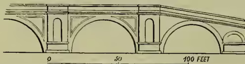
But the skilful and intelligent construction of a permanent bridge, with a large number of blocks of stone, in combination, held together mainly by the force of gravitation, was a problem of another order: apparently outside the scope of the Greek forms of constructive design, when the people of Athens crossed the Cephissus by wading or ferrying. But it was thoroughly grasped by the practical genius of the Romans, to whom, by general consent, the adoption of the arch as a constructive feature in works of architecture and of engineering is attributed. The Roman bridges generally consisted of a level road supported on one or more semicircular arches, exemplified in the Ponte de Rotto, or Senators' Bridge (fig. 1), erected by Caius Flavius, 127 B.C.—probably the first instance of the application of the arch in bridge design. The most remarkable bridge of antiquity was built by Trajan across the Danube, near Warkel, in Hungary, 4500 feet in length, 60 feet wide, consisting of twenty arches having a span of 170 feet, and 150 feet high from the foundations, constructed of squared stones. It was afterwards destroyed by Adrian, moved by jealousy probably, on the pretext that it would afford a passage for the barbarians into the empire. Some of the piers remain visible. The next considerable Roman work of this kind is the Pont du Gard, built in three stages, serving the double purpose of a bridge over the Gardon, and of an aqueduct for supplying the population of Nîmes with water. The bridge is 465 feet in length, and consists of six arches, which support a second series of arches, eleven in number, continued at each end to join the sloping sides of the mountains; and over these a third series, of thirty-five arches, much smaller than the lower arches, 850 feet in length, supporting a canal on a level with the mountains, 190 feet above the river. This unique structure was built with very large stones, worked with perfect accuracy to the required forms, and held together by iron cramps, without cement. It continues in a good state of preservation.
The semicircular arches of the ancients were succeeded by pointed arches, generally of small span; whilst in those of modern date the arches have generally been segmental—i.e. a segment of a circle less than a semicircle—or semi-elliptical. The segmental and elliptical forms are in general much the more suitable, as they combine wide spans and free waterway with moderate elevation. But they incur a much greater lateral thrust on the piers and abutments than the semicircular arch, which must of course be provided for in proportioning the form and mass of the supporting elements.
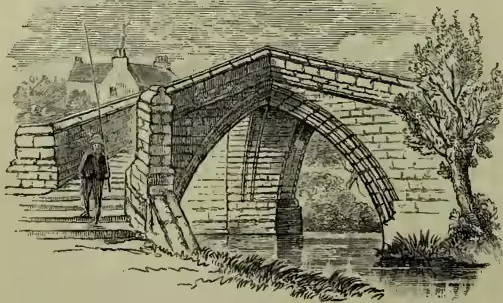
The Gothic 'triangular' bridge of Croyland, more properly 'trefoil' or three-way bridge (fig. 2), now usually called 'Trinity Bridge,' was built appar- ently about 1380 by the then abbot of Croyland in Lincolnshire (q.v.). It was erected at a point where a branch from the main stream of the Welland (1½ mile distant) divided into two smaller branches; and its three arches provided for three watercourses and three roadways. But it could never have been intended for heavy traffic, as it is too steep and too narrow for any vehicle. In 1854 the stream passing beneath, then become a common sewer, was arched over; and the bridge is now high and dry. On three piers or abutments arranged in a circle at the apices of an equilateral triangle, three semi-arches rise and meet in the middle—every two semi-arches balanced by the third. The longest bridge built in England in medieval times, was that over the river Trent, at Burton in Staffordshire, erected in the 12th century, of freestone, consisting of thirty-six arches, and 1545 feet long. It was superseded by a new bridge in 1864.
One of the most interesting bridges in the world is the bridge over the Taff, on the road from Llantrissant to Cardiff and Merthyr, which crosses the Taff at the village of Newbridge. It is named the 'Pont-y-tu-Prydd,' or Pontypridd, which means literally 'bridge by the earthen house,' derived from a mud hut that stood near the site. It was first determined to erect a bridge at a spot lower down the river; and William Edwards, a country mason, undertook the work, which was commenced in 1746. The bridge consisted of three arches; but two years and a half after it was finished, it was swept away during one of the great floods to which the Taff, like other rivers in mountainous districts, is subject; the water rising to so great a height as to flow over the parapet. Edwards, to guard against the danger which led to the destruction of the first bridge—the obstruction of the channel by the piers—conceived the bold design of spanning the river with a single arch of 140 feet span. The second bridge had barely been completed, when by another, but very different accident, the bridge fell like its predecessor. The quantity of material in the centre of the arch was so limited in proportion to that laid over the spandrils or haunches, that the deadweight on the haunches forced up the crown of the arch; and, again, the whole was reduced to ruins. After this second failure, most men would have relinquished the attempt. Not so with Edwards, who, persevering and ardent, determined on a third effort to overcome the difficulty. He rebuilt the bridge in conformity with the second design of a single arch; and profiting by experience, he adopted the precaution of greatly reducing the deadweight on the haunches, by making in each spandril three-through transverse cylindrical openings, from face to face of the bridge; and, in addition, he filled the internal spaces between the faces with charcoal, a material weighing not more than one-fourth of rubble stone, bulk for bulk. By this means, a permanent structure, finished in 1750, was reared, which has now lasted nearly 150 years. The arch is a segment of a circle; it measures 140 feet wide between the abutments, as already stated, and has a rise of 35 feet. The arch is not parallel faced, but is 14 feet 5 inches wide at the crown, widening to about 16 feet wide at the springing, or the abutments. This expanding form is an element of stability. The roadway is 11 feet wide at the crown. From the great rise of the arch, the roadway over it was uncommonly steep and even dangerous; and about 1830, the roadway was raised at each end, and the surface was paved. But even now it is so steep—the inclination being at the rate of 1 foot rise in 4 feet horizontally—that it is found necessary to use a chain and drag, so that when a carriage reaches the centre of the bridge, one end of the chain is attached to the hinderpart of it, the other end being secured to the drag, upon which a boy generally places himself, so that as the carriage descends upon one side, the drag is pulled up on the other side, and thus relieves the horse in descending. Edwards erected several other bridges in South Wales. With the occupation of a mason he combined that of a Methodist minister, having preached for upwards of forty years at White Cross Chapel, in his native parish.
The nature of the arch, with definitions, has already been noticed in the article ARCH. Each stone of an arch is acted on by three forces, one of which, its proper weight plus the weight of the load above it, is vertical. The second and third, the pressure of the two contiguous stones upon it, are perpendicular to the surface of contact with these stones. The nature of the stress everywhere is essentially compressive—that is to say, every individual stone acts and reacts by simple pressure—the result of gravitation. When every portion of the arch is equally stressed, no part tending to yield before another, it is in a perfect state of equilibrium. But, as says the old proverb, 'an arch never sleeps'—always ready for a fall—and if too great a load be placed on the crown of the arch, it will open outwards at the haunches, and sink inwards at the crown. If, on the contrary, there be a deficiency of weight at the crown, the crown will open upwards, and fall in at the haunches, as happened in the case of the second Pontypridd.
It is readily conceived that the higher the rise of the arch in proportion to the span, the less intense proportionally is the stress in its component parts, the less injurious is any slight inaccuracy of workmanship or design likely to prove, and the easier is the work of construction. But the inconvenience of the steep slopes resulting from a great proportionate rise of the arch, in situations where the approaches are low, has enforced the adoption of the lowest practicable rise and a low elevation of the roadways of bridges—segmental or semi-elliptical in form, as before stated.
The celebrated Grosvenor Bridge over the river Dee at Chester (fig. 3) supplies a fine example of a segmental arch of large span, the second largest span of a stone bridge in the world, the arch over Cabin
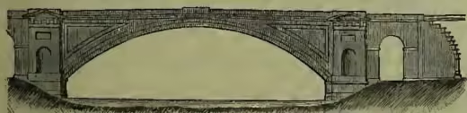
John Creek, in the Washington Aqueduct, being the largest, 220 feet. The old bridge connecting Chester with a suburb, Handbridge, first noticed in the 13th century, is recorded to have fallen down or been carried away twice. The third erection was of stone, in 1280, consisting of seven arches, pointed Gothic, supported on huge piers or buttresses. The old bridge has been aptly described by Ormerod, as 'a long fabric of red stone, extremely dangerous and unsightly, and approached by avenues to which the same epithet may be safely applied.' The new bridge was designed by Mr Harrison, a local architect. It consists of one arch of 200 feet span, and 42 feet of rise—a segment of a circle of 140 feet radius. The total length is about 345 feet, and the clear width of roadway is 33 feet. It is below the old bridge, and stretches from the rock below Chester Castle towards the village of Overleigh. The abutments are founded on the solid rock, except where a fault occurs from the rock dipping almost vertically, at the back part of the north end, and where filling was necessary. So soft was the material with which the fissure was filled, a kind of quicksand, that the piles went down 5 or 6 feet at a blow for a considerable depth. A floor of stone was laid on the head of the filling, and the abutment was built upon it. The arch stones are 4 feet deep at the crown, and gradually increase to 6 feet at the springing. The radiating courses of stones on the principle of the arch is carried through the abutments, even down to the foundations; and the rock itself becomes the actual abutment as shown in fig. 4. The bridge was constructed of native sandstone, excepting the faces of the abutment and the first two courses of the arch, which are of granite.
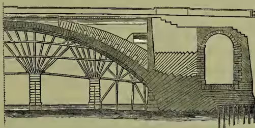
The centering (fig. 4) on which the stupendous arch was raised consisted of six ribs in width of fir timber. The span of the arch was divided into four spaces by means of three nearly equidistant piers of stone built in the river, from which the timber spread fan-like towards the soffit or under face of the arch, where they were bound together with thick planking bent round to the curve of the arch. On the rim thus formed, the lagging or covering to form the bed on which the stones were laid was supported over each rib by wedges, by means of which the bed could be adjusted to the true curve, and which were driven out when the bridge was completed in order to remove the centering. The framing of the centering was composed entirely of whole and half timbers, from 22 to 36 feet in length; and, in all, the centre used up 10,000 cubic feet of timber. The effectiveness of the system adopted was proved by the circumstance that half of the arch was turned before the centre was finished; and that on its removal, the crown of the arch sank only from inches to inches, the joints remaining perfectly close, and no derangement of form, or of 'spaulching' or cracking being perceptible. The cost of the centering did not exceed £500.
The Grosvenor Bridge was constructed in the course of five years, and was opened in 1832. The total cost of the work was £49,900, which included a sum of £7500 for the embankment forming the approaches, or £145 per lineal foot.
John Rennie led the way to the adoption of semi-elliptical bridges. His first important bridge—across the Tweed, at Kelso—opened in 1803, consists of five semi-elliptical arches of 72 feet span, with a rise of 28 feet, and four piers 12 feet thick, with a level roadway feet wide between the parapets, and 29 feet above the ordinary surface of the river. The foundations were laid on solid rock. The piers and abutments are ornamented with three-quarter columnar pilasters of the Roman-Doric order, surmounted by a plain block-cornice and balustrade of the same character. Kelso Bridge, as Dr Smiles observes in his Lives of the Engineers, may be regarded as the model of the greater work by the same engineer—Waterloo
Bridge. It was, he adds, one of the first bridges in this country constructed with a level roadway, contrasting vividly with the old-fashioned bridges, sloped like the roof of a house, as, for instance, the Pontypridd already noticed.
Waterloo Bridge, across the Thames, designed by John Rennie, has a level roadway, carried on nine equal semi-elliptical arches, of 120 feet span each, and 32 feet rise, leaving a clear height of 30 feet above high-water spring-tides. It was built of granite, in a style of solidity and magnificence previously unknown. Inverted arches were built between the elliptical arches in order to counteract the lateral pressure. The elliptical arch was carried to a greater extent of flatness than in bridges previously built. Isolated cofferdams upon a great scale, in a tidal river, with steam-engines for pumping out the water, were employed in the building of this bridge, for the first time, it is believed, in Britain. The length of the bridge between the abutments is 1380 feet, and the width between the parapets is 42 feet 4 inches. The long inclined approach on the Surrey side is formed by a series of thirty-nine semicircular arches of 16 feet span, besides an elliptical arch, of 26 feet span, over the Narrowwall Road, and an embankment 165 yards long, on an inclination of 1 foot rise in 34 feet of length. The total length of the bridge, with approaches, is 2456 feet, or nearly half a mile.
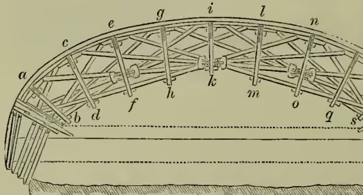
The bridge was finished in 1817. The centering employed in the erection of the arches is illustrated by fig. 5, and is an excellent example of centering supported at the piers. It may be observed that the loads on the upper face of the centering are resisted by oblique struts passing to the right and to the left, finally taking their bearing on the base of the piers. At each of the points c, e, g, &c. a pair of oblique struts is placed to take the thrust, one of them resting on a pier, the other lodged in the central shoe, k, and opposed by the corresponding strut from the other half of the arch. When the centres were struck, the sinking of the arches did not exceed from to inches at the crown.
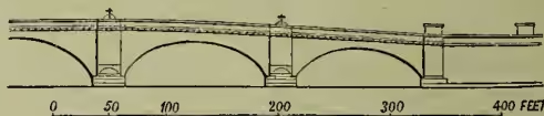
New London Bridge (fig. 6), across the Thames, was built 180 feet higher up the river than the old bridge. It consists of five semi-elliptical arches, the least of which is wider than any other elliptical arch ever before erected. The central arch has feet span, with feet rise; the next two arches are of 140 feet, and the two abutment arches are of 130 feet span. The roadway is 52 feet wide. The clear waterway at all times of the tide is 692 feet, or 60 feet more than the old bridge afforded at high-water. The whole length of the bridge is 1005 feet. At the City side the bridge is carried over Thames Street on a dry arch. At the Borough or south side the approach is formed on an inclined plane, supported on a series of brick arches, with a large dry arch facing Tooley Street. This bridge deserves further remark for the difficulty of the situation in which it was built, above the old bridge, in a depth of from 25 feet to 30 feet at low-water, on a soft alluvial bottom, covered with large, loose stones, scoured away by the force of the current from the foundations of the old bridge. The whole of these stones had to be removed by dredging before the cofferdams for the piers and abutments could be commenced; otherwise it would have been extremely difficult, if not impracticable, to have made them watertight. The difficulty was further increased by the old bridge being left standing, to accommodate the traffic whilst the new bridge was building, and the restricted waterway of the old bridge occasioned such an increased velocity of the current as materially to retard the operations of the new bridge. At times the tide threatened to carry away all before it; and it was found expedient that two of the small arches of the old bridge on each side should be thrown into one, to compensate for the additional obstruction which the water occasioned to the navigation. The piers and abutments stand upon platforms of timber, the floors of the cofferdams resting upon piles about 20 feet long. The masonry is from 8 feet to 10 feet below the bed of the river. The great magnitude and extreme flatness of the arches, of which the keystones are 4 feet 9 inches long, demanded unusual care in the selection of the materials, which were of the finest blue and white granite from Scotland and Devonshire, as well as great accuracy of workmanship. The new bridge was opened for traffic in August 1831, the period occupied in its erection, from the time of driving the first pile for the dam of the south pier, being seven years, five months, and thirteen days.
The centering employed for the new London Bridge is worthy of notice. It consisted of trussed timber girders, supported at the piers. The striking plates and wedges, by which the centre was lowered after the completion of the arch, were strong beams suitably notched, one of which, the wedge, was kept in its place by cross wedges. When the centre was to be lowered, the cross wedges were knocked out, and the main wedge driven back.
In the following table are given the leading dimensions of the largest stone arches that have been built for common roads, from 150 feet of span upwards:
| Name. | River. | Form. | Span. | Rise. | Keystone. | Date. | Engineer. |
|---|---|---|---|---|---|---|---|
| feet. | feet. | ft. in. | |||||
| Claix (Grenoble)..... | Drac ..... | Circular..... | 150 | 54 | 3 1 | 1611 | .... |
| Gloucester..... | Severn ..... | Elliptical ..... | 150 | 35 | 4 6 | 1827 | Telford. |
| London ..... | Thames..... | Elliptical ..... | 152 | 37½ | 4 9 | 1831 | Rennie. |
| Tourmon..... | Doux..... | Circular ..... | 157 | 65 | .... | 1854 | .... |
| Verona ..... | Adige..... | Elliptical..... | 160 | 53 | .... | 1354 | .... |
| Lavaur..... | Agout..... | Elliptical..... | 160 | 65 | 10 9 | 1775 | Saget. |
| Gignac..... | Hérault..... | Elliptical..... | 160 | 44 | 6 5 | 1793 | Garipuy. |
| Vieille-Brionde ..... | Allier..... | Circular..... | 178 | 69 | 5 3 | 1454 | Grenier and Estone. |
| Chester ..... | Dee ..... | Circular ..... | 200 | 42 | 4 0 | 1832 | Hartley. |
| Washington Aqueduct | Cabin John Creek. | .... | 220 | .. | .... | .... | Meigs. |
The development of the railway system, with command of plenty of capital, has afforded opportunities for the construction of bridges on a grander scale than for common roads. The largest railway bridges usually cross rivers or canals, the smaller single-arch bridges over or under local roads, and for field communication. The number of these is surprising. There are no fewer than 63 such bridges under or over the railway on the 30 miles between Liverpool and Manchester. There are 160 bridges over and 110 under the London and Birmingham line; on the South-Eastern line there are 141; and between London and Gosport, on the South-Western line, there are 188; making a total of nearly 600 bridges on 287 miles of railway, or over two bridges per mile.
The brick bridge over the Thames at Maidenhead, on the Great Western Railway, designed by Mr I. K. Brunel, supplies a remarkably daring instance of wide spans, combined with a low rise of arch. It consists of a central pier and two main arches, flanked at each end by four openings for the passage of flood-water. The main arches are elliptical, 128 feet span, with a rise of feet only. The land arches are semicircles, 28 feet in diameter. The central pier stands in the middle of the river upon a shoal which provided a good foundation, whilst the deep waterway was left free for the navigation. The low rise of the arches was imposed by the condition of the gradients.
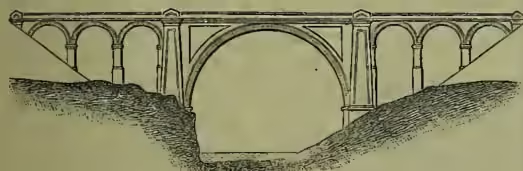
With the railway system, nevertheless, the semicircular stone arch has been revived in bridges as well as in viaducts. One of the most imposing structures of this class, forming part of the Glasgow and South-Western Railway, is the Ballochmyle stone viaduct (fig. 7), over the river Ayr, which spans the river by a semicircular arch of 180 feet span, founded on rock—the largest span of railway masonry in Britain or elsewhere—with six auxiliary arches of 50 feet span. The arch stones of the central arch are feet broad. The centering of timber erected for the construction of this arch was a masterpiece of carpentry, well worthy of careful study. Its principal members were composed of 14-inch square balks, carried up from the bed of the river, well braced by diagonals, especially transversely, as the height was very great in proportion to the width. Rails were laid at the upper part of the framing to carry the traversing cranes employed in the construction of the arch. The highest point of the centering stood 157 feet 4 inches above the bed of the river. The level of the rails on the viaduct is 167 feet high.
The Congleton Viaduct, on the Manchester and Birmingham Railway, is amongst the longest in Britain. It is of stone, 1026 yards, or more than half a mile in length, and 106 feet high. It cost £113,000, or £113 per lineal yard. The Dane Viaduct, on the same line, is of brick, 572 yards long, 88 feet high; and it cost £54,000, or £95 per lineal yard, having 23 arches of 63 feet span. On the railway lines entering London and other large cities and towns, there are miles of brick viaducts, extending often as far as the eye can reach. On the Vincenza and Venice Railway there is a viaduct (1845) of stone and brick, by which the
Laguna Veneta is crossed, consisting of 222 arches, and 12,000 feet, or more than two miles long. Thus is Venice, the ocean city, chained to the mainland.
Timber bridges, or frame bridges, as they are occasionally called, are now almost unheard of in Britain—particularly on railways, by reason of their want of durability; and such railway bridges as have in earlier times been built of timber in Britain, have for the most part been reconstructed of stone, brick, iron, or steel. Nevertheless, timber bridges are in some situations, in new and poor countries, practically the only works available where timber is abundant and cheap. It may be proper to place on record the frame bridge constructed at East Linton, on the North British Railway (fig. 8), as a masterpiece of construction, having stone abutments and timber arching, the timber being so disposed as to combine a perfectly stiff, unyielding platform with free circulation for air and economy of material.
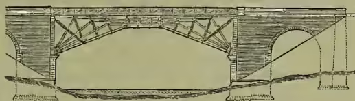
The main timbers are all in compression; there is nothing in tension, and struts are inserted by which the inclined timbers are firmly combined and stiffened to resist the compressive stress. It may be explained that this bridge, which is over the Haddingtonshire Tyne, was built originally with a stone arch, which fell and was replaced by the timber structure. A viaduct, having timber arches of long span, was erected on the line of the Manchester and Sheffield Railway over Dinting Vale, and opened in 1844. This viaduct consists of 16 arches, 5 of which are of Memel timber, each of 125 feet span, with 25 feet rise. There are four laminated main ribs in each arch, each feet deep, 18 inches wide, consisting of 3-inch planks laid longitudinally, firmly stayed together. The remaining 11 arches are of brick, of 50 feet span.
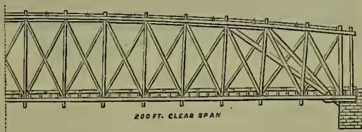
It is to the United States of America that we must look for examples of high-class timber bridges and viaducts on a large scale. The 'inflexible arched truss,' introduced by Mr D. C. McCallum, has probably been in more general use in the States than any other system of timber bridge. It is illustrated in fig. 9, showing one-half of a railway bridge of 200 feet span, 15 feet wide in the clear for a single line. The depth of the truss is 26 feet at the centre, 21 feet at the ends. Its cost is said to be from £6 to £8 per lineal foot.
Cast-iron Bridges.—Towards the close of the 18th century, some bridges were erected, the arches of which were constructed mainly of cast-iron. The first of these structures was the bridge over the Severn, near the town of Ironbridge, erected by Mr Darby, of Coalbrookdale Ironworks, in 1779.
The bridge consisted of a single arch, nearly semi-circular, of 100 feet span. The most celebrated bridge of cast-iron is Southwark Bridge, across the Thames, designed and erected by Mr Rennie, opened in 1824. It consists of 3 cast-iron arches, with stone piers and abutments. The arches are flat circular segments, the central arch having 240 feet span, with a rise of 24 feet, and springing at a level of 6 feet above high-water of spring-tides. The two side arches are of 210 feet span, with a rise of 18 feet 10 inches. The piers are 24 feet wide at the springings. There are 8 arched ribs in the width of the bridge. The arches are 2½ inches thick, and from 8 feet deep to 6 feet deep at the crown; they are in 13-feet lengths, bolted together and joined by transverse plates of the same depth. The roadway is 42 feet wide. The weight of the central arch is 1605 tons, and that of each side arch 1460 tons, making a total of 4585 tons of metal. The rise of the arch due to expansion by heat was observed to amount to 1¼ inches for 50° rise of temperature. The bridge is 718 feet long between the abutments.
Two railway bridges of a composite character, combining a cast-iron arch with plate-iron horizontal members, were designed by Sir John Fowler for the Coalbrookdale Railway, and the Severn Valley Railway, crossing the river Severn. Each bridge has a span of 200 feet, with a rise of 20 feet, consisting of 4 ribs for supporting a double line of way.
The high-level bridge over the deep ravine through which the Tyne flows between Newcastle most striking features of the bridge. It is suspended from the upper or railway roadway. There are 4728 tons of cast-iron in the bridge, and 321 tons of wrought-iron. The bridge cost £243,000, or, say, £176 per lineal foot. It was opened by the Queen in 1849. The first difficulty in building the bridge was to secure a good foundation for the piers. The first pile was driven to a depth of 32 feet in four minutes; and as soon as one was placed, the traveller hovering overhead presented another, and down it went, like a pin into a pincushion. When the piles had been driven and the cofferdams completed, the water was pumped out. But though powerful engines were employed, it forced itself through the bed of quicksand as fast as it was removed. Every effort was made for months to overcome it, but without success, until at last a bed of cement-concrete was laid in, a foundation was made, and the piers were built.
This bridge is historically interesting, as it shows a transitional form intermediate between the arch and the girder—between cast-iron structures and wrought-iron structures (see also the article NEWCASTLE).
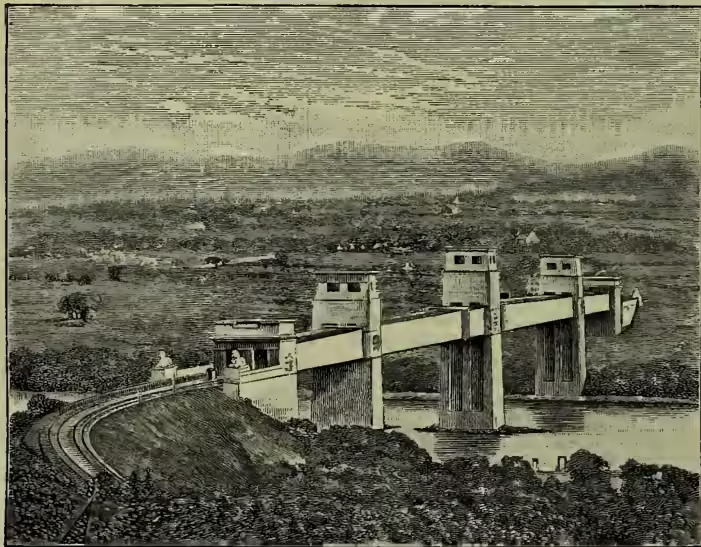
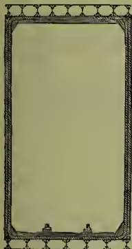
Wrought-iron Bridges.—The unsuitability of cast-iron as a material for bridges of very large span—long-span bridges as they are called—raised the question of the sole employment of wrought-iron as the material for the crossing of the Conway and the Menai Strait, on the line of the Chester and Holyhead Railway, involving spans of 400 feet and upwards. The maximum existing span in cast-iron—that of Southwark Bridge—did not exceed 240 feet; and for the greater spans Mr Robert Stephenson conceived the idea of wrought-iron tubes for crossing the Conway River and the Menai Strait in large spans, through which railway trains were to be conducted. Sir William Fairbairn devised and conducted the preliminary course of experiments required for the purpose of testing by models the strength of such a structure, with others of elliptical and rectangular section for comparison. Rectangular tubes had the advantage in point of strength, and a model beam accordingly was constructed, to a scale of one-sixth of the proposed bridge. It bore the test most satisfactorily, and showed that the proposed tube could be made self-supporting over the desired span of 460 feet. Arrangements were accordingly made for the erection of the colossal structure itself. The Britannia Bridge (fig. 10), so called after the Britannia Rock on which the central pier rests, was built across the Menai Strait. It consists of two independent continuous wrought-iron tubular beams, 1510 feet in length, weighing 4680 tons each, independent of the cast-iron frames inserted at their bearings in the towers. They rest on two abutments and three towers of masonry at a height of 100 feet above high-water. The middle, or Britannia tower, 230 feet high, is built on a rock in the middle of the strait. The bridge is thus in four spans, of which there are two spans of 460 feet over the water, and two spans of 230 feet over the land. The weight of one of the longer spans, single tube, is 1587 tons, and that of one of the shorter spans 630 tons. The average weight of a single tube is over three tons per lineal and Gateshead is a unique structure in cast-iron, a fine example of the bow-string arch. It formed the junction between railways from York and from Berwick, then separate (now the North-Eastern main line). It was proposed by Mr Hudson, the railway king, and designed by Mr Robert Stephenson and Mr T. E. Harrison. There are two roadways—one for carriages and foot-passengers, level with the Castlegarth, and the other, 22 feet above it, for railway traffic. The bridge consists of six spans of 125 feet each; the piers, 16 feet thick, being of masonry, the arched ribs of cast-iron, and the ties of wrought-iron. The soffit or under side of the roadway is 83 feet above high-water. The total height of the piers is 131 feet from the foundation. The carriage-road is 1380 feet in length—about a quarter of a mile. It forms one of the foot of advance. A transverse section of each tube is shown by fig. 11. The chief mass of the material is placed at the top and the bottom, represented by the upper and lower flanges or tables of an ordinary beam, the two sides serving to connect the top and the bottom. Constructed of plate-iron, the top requires more metal than the bottom, in order to resist the buckling stress to which it is subject. But, instead of putting the metal into one thick plate, or into several plates laid one on another, it is constructed to form a set of small tubes or cells, which give additional stiffness and strength to the whole tube. The floor, in like manner, contains cells. Each tube is straight on the lower face, and slightly curved on the upper face, inasmuch that the height of the tube externally is 30 feet at the middle in the Britannia Tower, and 26 feet internally, and 22 feet 9 inches and 18 feet 9 inches at the extremities in the abutments. The width of each tube externally is 14 feet 8 inches, and 13 feet 5 inches clear inside. The side plates are from inch to inch in thickness; the top plates are from inch to inch, for resisting compression; and the bottom plates are from inch to inch thick, for resisting extension. The tubes repose solidly on the centre tower, but on the land towers and abutments they repose on roller beds, thus permitting free expansion and contraction according to the temperature. The daily variation of length is from inch to 3 inches for the whole length of the tube, the extremes of the movement being attained at about 3 P.M. and 3 A.M. The effect of sunshine in deflecting the Britannia Bridge, as observed by Mr Edwin Clark, is very curious. A short spell of sunshine on the top of the tube raised it on one occasion nearly an inch in half an hour, with a load of 200 tons at the centre, the top plates of the bridge being expanded by increase of temperature, while the lower plates remained at constant temperature by radiation to the water beneath them. In like manner, the tube was drawn sideways to the extent of an inch by the sun shining on one side, and it returned immediately to its normal position as clouds passed over the sun. The tubes sometimes move as much as inches vertically or horizontally when the sun shines on them. The tube is in fact a most delicate thermometer, in constant motion, both vertically and laterally. The Britannia Bridge was opened in March 1850 by the passage through it of three powerful locomotives with tenders. The second experimental train that went through consisted of twenty-four heavily laden coal-wagons, aggregating 300 tons weight. The train was drawn through the tubes at leisurely speed. During the passage a breathless silence prevailed, and when the train emerged at the other end the event was announced by great cheering, mingled with the reports of pieces of ordnance. One can imagine the relief from intense anxiety to the engineer. 'Often at night,' said Mr Stephenson, 'I would lie tossing about, seeking sleep in vain. The tubes filled my head. I went to bed with them, and got up with them. In the gray of the morning, when I looked across Gloucester Square, it seemed an immense distance across to the houses on the opposite side. It was nearly the same length as the span of my tubular bridge.'
A similar tubular bridge across the Conway, on the line of the Chester and Holyhead Railway, was designed and erected by Mr Stephenson. It consists of two tubes, each of one span of 400 feet, and was opened for traffic in May 1848.
The Victoria Railway Bridge (1854-59) over the St Lawrence River, at Montreal, Canada, is tubular in design, like the Britannia Bridge. It is 9144 feet, or nearly miles in length, in twenty-four spans of 242 feet, and a central span of 330 feet. The total length of each of the tubes is 6592 feet; and there are 9044 tons of iron in the tubes, or about 1 ton per lineal foot. There is a total painted superficies equal to 32 acres. The river is 8660 feet, or about miles wide at the crossing, where it descends at the rate of 7 miles per hour. The bridge is remarkable chiefly for its ice-breaking piers, which are constructed with large bows at the up-river ends to resist the enormous pressure of the ice in spring. The rails are 60 feet above the level of the river.
Although tubular bridges are not likely to be constructed in the future, it should be remembered that it was in tubular bridges that the first attempt was made to introduce wrought-iron in long spans upon railways. This was done by Mr Stephenson at a time when perhaps it would not have been in the power of any other man to influence the introduction of wrought-iron in such structures. The experience of the tubular bridge, nevertheless, has led to a development of plate-iron girder bridges, in which the cellular principle of the tubular bridge has been applied in the designing of the longitudinal girders or beams between which the roadway is carried. The early forms for such girders are typified in the wrought-iron girders of the Torksey Bridge, Lincolnshire, erected in 1850. The bridge is constructed of two spans of 130 feet each. The girders are of uniform depth—10 feet. The upper boom or member of each girder is cellular, being the form best adapted to resist compression, and is constructed of plates inch and inch in thickness. The lower boom is not cellular like the top, as it is exposed only to tensile stress, and is constructed of plates inch and inch thick, riveted together. The two side plates, inclosing a hollow space, are made of -inch plates.
Lattice-girder Bridges.—The iron lattice bridge—so called from having sides constructed with cross-bars, like lattice-work—is the natural outcome of the tubular bridge for long spans, developing equal strength with considerable economy of material and labour.
Lattice bridges of timber were first used in America, where timber is cheap. The first lattice-girder in iron was designed by Sir John MacNeill, and erected in 1843 on the line of the Dublin and Drogheda Railway, near Dublin, of 84 feet span.
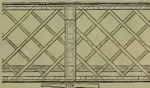
Lattice-girders are now almost universally adopted for iron bridges for long spans. Amongst the earliest of them is the lattice bridge forming a portion of the Boyne Viaduct on the line of the Dublin and Belfast Junction Railway, near Drogheda, completed in 1855. It has three large openings, of which the middle span is 264 feet long, and the side spans 138 feet. There are two side girders 26½ feet deep, 24½ feet apart, connected by cross girders of lattice-work above and below—forming a rectangular inclosure, within which, on a platform, two lines of rails are laid on which the trains run. Each of the lattice-bars is crossed by six others at the angle 45 degrees, forming squares (fig. 12).

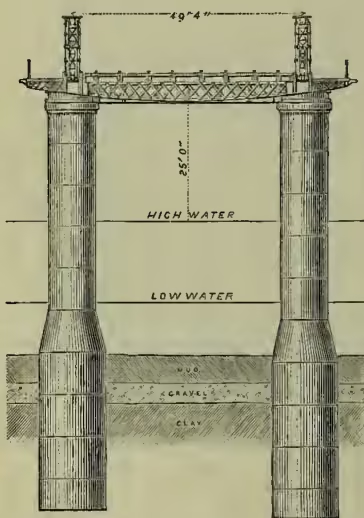
Charing Cross Bridge: one of the Piers.
The Charing Cross Bridge across the Thames, on the line of the South-Eastern Railway (fig. 13), is a lattice bridge of a different order, having a total length of 1365 feet, over a quarter of a mile. It consists of nine spans, six of which are 154 feet clear, and three are 100 feet clear. In the superstructure of each opening of 154 feet there are two main girders, 49 feet 4 inches apart transversely between their central lines, connected beneath by transverse girders, carrying four lines of rails, and projecting at each side to carry a footpath. The main girders are 14 feet deep. The sides are constructed of top and bottom booms of plate-iron, and are in panels divided by vertical bars, each panel containing two diagonal bars, crossed at the angle 45 degrees, and fastened to the booms by means of large round pins or bolts from 5 inches to 7 inches in diameter. The weight of one main girder is 190 tons. The bridge was built on the site of Brunel's old Hungerford Suspension Bridge, the two brickwork piers of which were utilised for the present bridge. The piers for the spans of 154 feet, other than the brick piers, are cast-iron cylinders, 10 feet in diameter above ground, and expanded to a diameter of 14 feet in the ground, thus supplying a very wide base for each cylinder. Each pier consists of two such cylinders (fig. 14), one for supporting each main girder. The piers are formed of segmental cast-iron plates bolted together, and they were sunk further depth of 4 inches into the clay. Altogether there are nearly 7000 tons of metal in the bridge. The total cost of the bridge, including the abutments, was £180,000, or £131 per lineal foot. The bridge thus at first constructed has recently been doubled in width to meet the development of traffic. For the Tay Bridge, see DUNDEE.
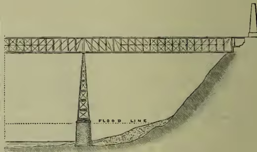
Bridge across the Kentucky River—Half Length.
American Quadrangular Girder Bridges.—One of the best examples of American long-span iron-bridge construction (fig. 15) is the bridge across the Kentucky River on the Cincinnati Southern Railway, designed by Mr C. Shaler Smith—noteworthy for the economical design and comparatively light weight. The ironwork of the bridge is 1138 feet in length, and it consists of three spans of 375 feet each. It crosses a limestone cañon at a height of 280 feet above the bed of the stream. The piers are of stone to a height of 60 feet, to clear the highest recorded floods; and they are about 34 feet thick at the flood-level. Above the stonework the piers are of iron. The truss or girder is rectangular in section, 37½ feet high, 18 feet wide, consisting of top and bottom pairs of booms, forming the corners, united by panels or frames at intervals of 18½ feet longitudinally, stiffened and bound with diagonal tie-rods. The booms each consist of flat plates placed vertically, riveted together. The piers consist of hollow pillars of plate-iron riveted together in box form. The diagonal rods are 'pin-connected'—that is to say, they are connected to the framework with cylindrical pins, a form of connection much practised in the States. The bridge was completed in February 1877. The expansion and contraction of the bridge operate each way from the centre, bending the tops of the piers correspondingly towards or from the shores; the greatest observed movement being half an inch either way. The ends of the girder rest by means of rollers on the abutments, and they have a maximum of 3 inches of travel resulting from variation of temperature. The ironwork of the bridge weighs 1631 tons, or 1.43 tons per lineal foot—less than half the weight per lineal foot of the tubes of the Britannia Bridge.
Cantilever Bridges—The Forth Bridge.—The principle of the cantilever bridge has already been noticed as applied primitively in Japan and India, and in China also. A cantilever is, as Baker has said, a bracket; a structure overhung from a fixed base. The bridge across the river Forth (fig. 16), on the North British Railway system, opened by the Prince of Wales, 4th March 1890, is the largest and most magnificent bridge in the world. The engineers were Sir John Fowler, K.C.M.G., and Sir Benjamin Baker. The site of the bridge is at Queensferry. At this place, the estuary of the Forth is divided by the island of Inchgarvie into two channels, whose depth, as much as 200 feet, precluded the construction of intermediate piers.
Hence, two large spans of 1700 feet each were adopted. Between these, the central pier is founded on the island midway across, and is known as Inchgarvie pier. There are two other main piers—shore-piers—known respectively as the Fife pier and the Queensferry pier. On these three piers respectively three double lattice-work cantilevers (fig. 17), like scalebeams, cylindrical columns of masonry 36 feet high, each 49 feet in diameter at the top, and 55 feet at the bottom, founded on rock or on boulder-clay. To make assurance doubly sure, the superstructure is bolted down to each column with forty-eight steel bolts 2½ inches in diameter and 24 feet long.
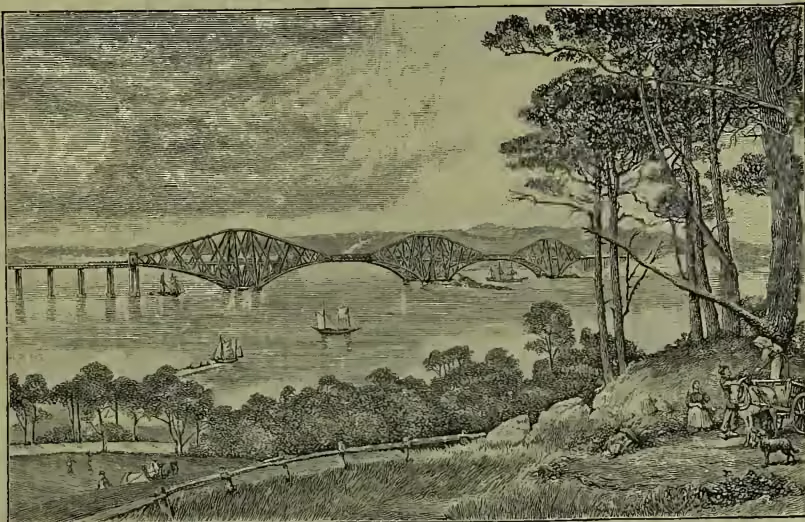
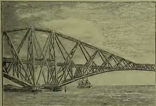
The piers were founded by means of Cofferdams (q.v.) for shallow depths under water, and Caissons (q.v.) worked with compressed air for the deep water at Inchgarvie and at Queensferry. At Inchgarvie, two caissons constructed of wrought-iron plates, 70 feet in diameter, were sunk, the rock being excavated from below the lower edge of the cylinder, to a depth of 72 feet below the waves of the Forth. The operations were conducted under the pressure of compressed air in a mining-chamber 7 feet high, lighted by electricity, at the lower end of the caisson. A striking incident served to impress the reality of the high pressure of the air in this chamber. A flat-sided spirit-flask was taken down and emptied. The bottle of course was filled with compressed air, of a pressure of 33 lb. per square inch, and was corked. Under this pressure it exploded when passing through the Air-lock (q.v.) into the open air. At Queensferry, four caissons like those employed at Inchgarvie were sunk to depths of from 71 to 89 feet below high-water. The bed of the river was of soft mud, through which the caissons were sunk into hard boulder-clay. The mud, after having been diluted with water, was blown out by the compressed air supplied to the mining-chamber. The caissons were gradually filled with concrete as it was required, to steady them, and at the same time to drive them down by deadweight through the clay. When they were sunk to the required depth, the bottom or mining-chamber was cleared out and rammed with concrete, grouted up under pressure. No subsidence took place after this final operation, the boulder-clay being very hard. But independently of this consideration, it is readily seen that by in this way substituting the whole area of the immense circular caisson for the mere circular cutting-edge at the bottom to take a bearing on the clay, the bearing surface, and with that the resistance to a vertical load, was almost indefinitely increased. When the concrete was filled to the water-level, the piers were carried up with massive stones laid in cement, the whole pier becoming one solid mass. 1360 feet, or a quarter of a mile in length, are poised in line, reaching towards each other, and connected at their extremities by ordinary girders 350 feet long, by which the two main spans are completed. The bridge consists of two main spans of 1700 feet, or nearly one-third of a mile each; two of 675 feet each, being the shore-ends of the outer cantilevers; and 15 spans of 168 feet each. The total length of the viaduct, including piers, is 8296 feet, or a little over 1½ miles, of which almost exactly 1 mile is covered by the great cantilevers. The clear headway under the centre of the bridge is 152 feet at high-water, and the highest part of the bridge is 361 feet above the same level. Each of the three main piers consists of a group of four
The bridge is taper in plan, each span narrowing from a width of 120 feet—the distance apart of the lower members of each cantilever—at the pier, to a minimum of feet at the extremities of the cantilever, giving an outline, in a vertical view of it, like a truncated triangle, in order to confer a degree of stiffness laterally, for resisting irregular stresses, wind-pressure in particular. The metal columns above each pier, forming the basis of the cantilever, are 12 feet in diameter. The members under compression are tubular, those in tension are of open braced forms. The wind-pressure is assumed from calculation at a maximum of 56 lb. per square foot. The maximum possible stress on any member of the bridge is calculated to be at the rate of tons per square inch of sectional area, leaving a plentiful margin of strength, since the steel of which the bridge is constructed is capable of resisting a tensile stress of from 30 to 33 tons per square inch, and compression to the extent of from 34 to 37 tons per square inch. Between the two main girders a double line of railway is carried on an internal viaduct supported by trestles and cross girders. The whole of the metal-work of the superstructure is of Siemens steel. The way will consist of heavy bridge-rails laid on longitudinal sleepers bedded in four steel troughs, into which the wheels will drop in case of derailment, when they will run on the sleepers.
In the piers there are about 120,000 cubic yards of masonry, and in the superstructure 44,500 tons of steel. The bent steel plates which go to make the tubes and struts would, if placed in a line, end to end, stretch a distance of 42 miles. There are 20 acres of surface to be painted. The contract was let for the sum of £1,600,000, or £215 per lineal foot. An impression of the great magnitude of the bridge is derived from a comparison with the largest completed railway bridge in England—the Britannia Bridge, which has spans of 460 feet—little more than one-fourth of the spans of the Forth Bridge. The best proof of approval is imitation. In this connection mention should be made of the fine organisation of labour secured by Sir Wm. Arrol, of Tancred, Arrol, & Co., the contractors, and of the ingenious special tools designed by him for carrying out the work of construction. Since the first publication of the design for the Forth Bridge, nearly every new long-span bridge throughout the world has been built on the principle of that design.
For comparison with the largest bridge in the world, the following particulars of a few mammoth railway bridges are given :
| Length. Feet. |
Greatest Span. Feet. |
|
|---|---|---|
| Forth Bridge ..... | 8296 | 1700 |
| Brooklyn Bridge..... | 5959 | 1595 |
| Niagara Bridge ..... | .. | 821 |
| Britannia Bridge..... | 1510 | 460 |
| Victoria, Montreal..... | 9144 | 330 |
| Boyne Viaduct..... | 1760 | 264 |
| Tay Bridge ..... | 10,780 | 245 |
| Charing Cross Bridge ..... | 1365 | 154 |
| Crumlin Viaduct, Monmouthshire ..... | 1800 | 150 |
| High-level Bridge, Newcastle-on-Tyne. | 1380 | 125 |
| Ann-Daria Bridge ..... | 6320 | .. |
| Memphis Bridge (over Mississippi) .. | 1856 | 790 |
| Cernavoda Bridge (Danube) ..... | 2350 | 600 |
| Sukkur Bridge (Indus) ..... | 1250 | 785 |
The latter has cantilevers each 320 feet long.
Suspension Bridges.—These are bridges in which the roadway is suspended from chains, links, or ropes, passing over piers or towers, and fixed or anchored at their extremities. Another line of evolution had its origin in the principle of suspension. The simplest form, if possible, is a rope, traversed by a pulley, ring, or grooved block of wood, from which a rude car is suspended, or, in some cases, only a loop, in which the passenger sits, and either works himself across with his own hands, or is drawn from side to side by a smaller line attached to the car. Such elementary bridges have been in use from the earliest ages. More than a hundred and thirty years ago, Don Antonio de Ulloa described them as commonly used in the mountainous districts of South America. Structures of a more bridge-like character were erected by the Peruvians. Six strong cables are suspended across the river, four of which carry the platform, consisting of sticks laid across them, and branches of trees laid longitudinally upon the sticks. The two other ropes are considerably higher than the platform, and are connected with it. They serve as rails for the security of the passenger. Ulloa observes that 'the appearance of the bridges, which move with the wind, and are agitated by the movements of every passenger that crosses them, is very frightful at first.' They cross chasms hundreds of feet deep, through which cataracts of water, derived from the melting snow, rush, lashed into irresistible fury.
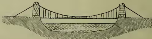
Fig. 18 is a typical illustration of a modern suspension bridge. When the weight of the roadway is known by the stress on the suspending links, the problem of statical equilibrium assumes the simplest form, and the conditions of strength and stability are readily determined. But when there is a shifting or rolling load on the roadway, which is heavy in proportion to the weight of the bridge, as, for example, a railway train, the conditions are involved. When the train occupies, say, only one-half of the bridge, the chain is depressed on that side, and is raised on the other side. Thus an undulation is produced in the bridge, which, especially if the train be moving rapidly, may seriously disturb the equilibrium, and even endanger the stability of the bridge. Various combinations have been devised to overcome this difficulty. The simplest and probably the best course is to stiffen the roadway, so that the stress of the passing load may be distributed over a considerable length of the chain. In this manner large railway bridges have been constructed in America—for example, the Roebling's bridge (1855) over the Niagara, miles below the falls, having a span of 822 feet, and being 245 feet above the level of the stream. A hundred yards higher up is a new cantilever railway bridge (1883).
The Menai Suspension Bridge, designed and constructed by Thomas Telford, was as great a step, in its own time, as its neighbour the tubular railway bridge of Robert Stephenson. After various abortive designs were proposed and abandoned, Telford put forward his plan for crossing the straits by a suspension bridge of one large span, 100 feet high above the water-level. The roadway is suspended from four cables, each consisting of four tiers of bars, making in all sixteen chains, having a drop of 57 feet, or about one-tenth of the span. There are two carriage-ways, each 12 feet wide, with a footpath between them, 4 feet wide. The chains consist of flat bars on edge, 10 feet long, 1 inch thick, and inches wide, connected to each other by round bolts. The total length of the bridge is 1710 feet, or about one-third of a mile; and the distance between the points of suspension is 579 feet. The total weight of iron used for the structure was 2187 tons. The bridge occupied six years in construction, and was opened in 1825. The total cost, including the embankment and about half a mile of new line of road, was £120,000.
The success of the Menai Suspension Bridge having been assured, one of a still larger span, 870 feet, at an elevation of 167 feet above the river, was constructed at Freiburg, which crosses the valley of the Sarine, in Switzerland. The bridge was suspended by wire-ropes, each consisting of eighty wires, inch thick, tied together by coils at intervals. The bridge was finished in 1834. There is a similar, but rather smaller, bridge over the Gotteron, a tributary of the Sarine.
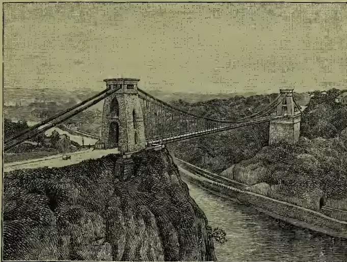
The Clifton Suspension Bridge (fig. 19) has an interesting record. In 1753 William Vick, a Bristol alderman, bequeathed the sum of £1000, to accumulate at compound interest until it reached £10,000, and then to be used in constructing a stone bridge at or near the site of the present Clifton Bridge. This sum was augmented by contributions, and in 1830 an act was obtained for the construction of the bridge, to the design of Mr Telford, having a central span of 400 feet. The work subsequently passed into the hands of Mr I. K. Brunel, a man of large ideas, who made a new design for a single span of 702 feet, at a height of 250 feet above high-water level. The new design was proceeded with in 1836, and the abutments and piers were completed; but, for want of funds, the work was arrested until 1860, when advantage was taken of the removal of the old Hungerford Suspension Bridge, to make room for the Charing Cross Railway Bridge. The chains were bought at a low cost, and in 1861 the works of the
Clifton Bridge were resumed, in which the old chains were utilised. In the new bridge there are three chains on each side, supporting longitudinal stiffening girders of wrought-iron, with open-work cross-girders to carry the floor of the bridge. The hand-railing was also ingeniously utilised with lattice-work as a girder to co-operate in stiffening the platform. The span of the bridge, measured between the centres of the piers or towers, is 702 feet; the width is 31 feet, including 20 feet of roadway defined by the distance apart of the chains, and two footways, one at each side. The roadway is not on a dead level, but between the piers has a rise or arching of 2 feet. The chains, passed over the piers on cast-iron saddles or rollers, are carried downwards to land-saddles at a distance of 196 feet from the piers, bedded on brickwork set upon the solid rock. Sixty feet further the chains are carried down at an angle of 45 degrees to the anchorage-plates, bedded in a mass of brickwork in the form of an arch abutting on the solid rock far below the surface of the ground. All the links were proved with a stress of 10 tons per square inch. The platform is suspended by vertical rods from the chains, and that the stress on the rods may be adjusted and equalised, they are fitted each with a double adjusting screw at the lower end. The roadway is of creosoted timber 5 inches in thickness. The footways are laid with timber of half this thickness. The weight of the chains between the piers is 554 tons; and yet they are subject to a tensional stress of 680 tons at the middle, by their own weight. The suspension-rods, girders, flooring, &c., weigh 440 tons, making, with the chains, a total weight of nearly 1000 tons. It is calculated that, if the bridge be loaded all over the platform at the rate of 70 lb. per square foot, which is estimated as the maximum weight of a crowd, the final stress on the chains at the middle would amount to 2094 tons, or 4 tons on each square inch of section of the chains. In order to provide for the effects of expansion and contraction and other causes of disturbance, the two ends of the roadway are furnished with hinged flaps 8 feet long, which give perfect freedom of movement vertically as well as horizontally.
The Brooklyn Suspension Bridge across the East River, between New York and Brooklyn, opened in 1883, is built of steel. It has a central span of 1595 feet, and two land spans of 930 feet each; making, with the approaches, a total length of 5989 feet, or about one mile and one furlong. The anchorage at each end is a solid cubical structure of stone, measuring 119 feet one way, by 132 feet the other, rising to a height of 90 feet above high-water mark, weighing 60,000 tons each. The towers are 276 feet high. The weight of the whole structure suspended between the towers is nearly 7000 tons. The stress of suspension is borne by four cables, of 5000 steel wires each, 15 inches in diameter. The foundations of the towers were laid by means of caissons and compressed air, at a level of about 80 feet below high-water mark. The roadway presents five parallel avenues, of an average width of 16 feet each. The two outmost avenues, 19 feet wide, are devoted to vehicles; the central avenue, 15 feet wide, for foot-passengers; and on the two intermediate avenues are laid tramways for car-traffic. For illustration see BROOKLYN.
Movable Bridges.—Movable bridges are usually required in the neighbourhood of rivers, docks, wharves, canals, and like situations, for the passage of ships and boats. They are variously designed and adapted to particular situations, and may be classified as: (1) Bascules or drawbridges, (2) swing bridges, (3) traversing bridges, (4) lift bridges, (5) pontoon bridges.
Bascules or Drawbridges.—The bascule bridge is such as is raised by turning, in one piece or in two pieces, round one or two horizontal axes or hinges. The most ancient form of the bascule was that of one flap of framed timber used to cross the moat or ditch of a fortress or castle, and capable of being drawn up by means of chains from the inside. For large dimensions it is convenient to construct the bridge in two halves, lifting from each side, and abutting together at the middle. An excellent bascule bridge, erected in 1839, on the North-Eastern Railway, across the river Ouse, gives a clear water-way of 45 feet. The bridge is opened by two men, one at each leaf, in about one minute and a half, and is opened about eight times every day. One of the largest bascule bridges is that at Copenhagen, which was opened for traffic in 1867, giving a free passage-way of 56 feet 8 inches. The bridge is counter-weighted with 57 tons load at the end of the tail, which is feet from the centre of the hinge.
The Tower Bridge, a bascule bridge, across the Thames, at the Tower of London, opened in 1894, is constructed on such a scale as to be the largest bridge in the world of the bascule class. It is illustrated by fig. 20. The bridge may be the architect, and Mr J. Wolfe Barry is the engineer.
Swing Bridges.—Swing bridges are by far the most commonly employed of movable bridges. The large rivers to be crossed in America have demanded swing bridges of great span, with excellent contrivances for minimising friction and insuring steadiness when closed. The swing bridge over the Raritan, in New Jersey, U.S., allows two free passages, each 216 feet wide. It is what is known as a double-swing bridge—the bridge being balanced on a central pivot assisted by a system of rollers—opening and closing two passages at once, and affording two passages instead of only one, as in the earlier bridges, which were generally made in two leaves to cross single passages. The Kansas City Bridge crosses two passages, each 160 feet wide. The total moving weight is 303 tons. The bridge is opened by steam-power in about one minute and a half, or by manual power in two minutes. From two-thirds to three-fourths of the moving weight rests on the central pivot.
Traversing Bridges.
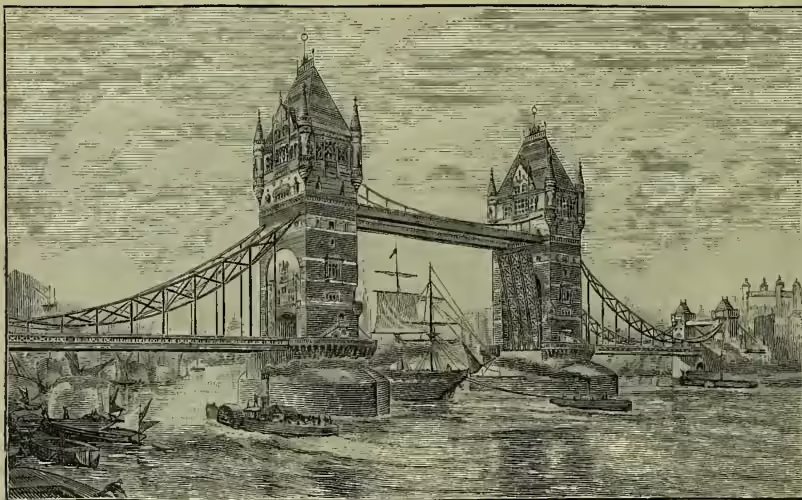
—Movable bridges, sometimes called telescope bridges, capable of being rolled horizontally backward, or in an oblique direction, are occasionally employed. The bridge across the Arun, near Arundel, on the South Coast Railway, is 144 feet long. It is traversed 'on wheels, and acts as a sliding cantilever, the over- described as a compound suspension and bascule bridge of three spans, of which the centre opening is fitted with a bascule or drawbridge, shown lifted in the figure. The bascule is carried by two massive Gothic towers, from which the chains or links are suspended, and in which provision is made for the machinery required for opening and closing the middle span. Lifts at both sides, as well as internal staircases, are provided for the use of foot-passengers. The lifts communicate immediately with the upper footway connecting the towers, so that the foot-traffic is never interrupted. The leaves of the drawbridge, when open, will be flush with the towers, allowing the largest shipping to pass through. When the bridge is closed, there will be sufficient height at high-water for the ordinary traffic of the river to pass under. The bridge has been built of gray granite for the lower portions, hard red brick for the upper portions of the towers. The opening of a passage for vessels, and the closing of the bridge, may be accomplished in the course of four or five minutes. Of the three spans, the clear centre opening for shipping is 200 feet, the side spans are each 270 feet, and the total length between abutments is 800 feet. The headway of the centre span when closed is feet above Thames high-water, and that of the side spans is 27 feet. The height of the foot-bridge across the centre span is 135 feet above high-water. The approach-roads and the foot-bridge are 60 feet wide. The parliamentary estimate cost of the bridge, including land, is £750,000, or about £940 per lineal foot. The late Sir Horace Jones was hanging portion resting on the opposite abutment when in place.
Lift Bridges.—These are not common. There appear to be only two—one erected over the Surrey Canal, which is lifted by the four corners; and another over the Royal Canal, Dublin. In the second case, a branch railway crosses the canal at an angle of 25 degrees. The bridge first made for the situation weighed 14 tons, and was balanced by a counterpoise consisting of a tank filled with water, the counterpoise, empty, being 1 ton lighter than the bridge, and when loaded with 2 tons of water, 1 ton heavier. The bridge could thus be raised and lowered with the aid of a man at a winch. The lift of the bridge was feet, which gave a headway for barges equal to that of the adjoining stone bridge. The supply of water for working the bridge was taken from an adjacent lock. At the four corners rams worked into cylinders, which admitted water from the lock to enter through small holes, and fill the cylinders as the rams were drawn up in the raising of the bridge, acting as a check in case of accident. The bridge has been reconstructed for a greater lift.
Pontoon or Floating Bridges—Bridges of Boats.
—Bridges of boats are made of boats laid over with planks, fastened across the stream by means of anchors or stakes. The bridge at Rouen is 300 yards long, paved with stone for the passage of carriages and horses. The so-called 'flying bridge' is rather a ferry than a bridge of boats (see FERRY).
A well-known pontoon bridge was designed by Mr Mallet to cross the Royal Canal at the Broad- stone terminus of the Midland Great Western Railway of Ireland. The general idea is that of a pontoon or flat-bottomed boat of iron. When the bridge is in place, water is admitted until it settles down firmly on timber wall-plates. To open it the water is drawn off by a movable siphon, which is connected with a fixed pipe, having a considerable vertical fall. A smaller branch pipe is set at an angle to the exhaust-pipe, and through it a strong jet of water is allowed to issue. This operation, on a well-known principle of hydrodynamics, sucks away the air from the siphon and causes it to act. The bridge then floats, and is drawn into a recess, leaving the passage clear along the canal.
The longest floating bridge in the world, probably, is the pontoon bridge across the river Hooghly, at Calcutta, designed and constructed by Sir Bradford Leslie. The bridge is 1530 feet long between the abutments, and is carried on 14 pairs of pontoons, which are held in position by means of chain-cables, inches thick, and anchors weighing 3 tons each, laid on the up-stream and down-stream sides, 900 feet asunder. By their great length, the cables afford the necessary spring to allow for the ordinary rise and fall of the river, the stress on each cable varying from 5 tons to 25 tons, according to the state of the weather and of the tide, the maximum velocity of which is 6 miles an hour. The pontoons are rectangular iron boxes, having rounded bilges and wedge-shaped ends. They are each of the great length of 160 feet, made of such considerable length in order to obviate pitching motion in rough weather, with a beam of 10 feet, and depth of from 8 to 11 feet, presenting a side of from to 4 feet above water, according to the state of the traffic. For perfect safety, each pontoon is divided by bulkheads into 11 compartments. They are made of iron plates inch and inch in thickness, riveted together. The platform of the bridge is supported by tressel-work on the pontoons at a clear height of 27 feet above the water—a convenient height for boat navigation. The roadway platform is of 3-inch planks of teak-wood from Burma, forming a roadway 48 feet wide, with a footpath at each side, 7 feet wide. An opening 200 feet wide, for the passage of ships, is made by removing, when occasion requires, four of the pontoons with their superstructure, and sheering them clear of the opening. The portion so removed is in two divisions, which are separately secured, right and left, and when in place, are connected by draw-bridges with the fixed portions of the bridge. Before launching, the pontoons were ballasted sufficiently to make them float upright; and were afterwards coupled in pairs by the cills of the main trusses, when the ballast was removed. The floating bridge is connected with the shore at each end by adjusting ways hinged to the shore. The ordinary time taken to open the bridge is 15 minutes; and to close it, 20 minutes. It is only opened twice a week. The bridge cost £182,000, or about £120 per lineal foot.
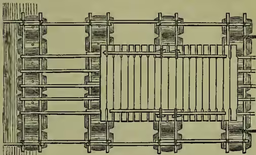
MILITARY BRIDGES are temporary constructions to facilitate the passage of rivers by troops, to restore a broken arch, or cross a chasm of no very great width. Those over a river are either floating or fixed. The former are made of Pontoons (q.v.), boats, casks, rafts of timber, or anything that will give sufficient buoyancy, and the latter of piles, tressels, or other timber work. Spars, ropes, and planks are used in a variety of ways for spanning narrow chasms. The pontoon bridge is the only one which is carried with an army. Enough material for 100 yards of length accompanies each army corps. All military bridges have their roadway formed in the following manner: five to nine road-bearers of stout timber support chesses or flat planks 10 feet long, held in position so as to form a level surface, by two ribands placed above them and over the outer road-bearers, to which they are fastened by rack-lashings. The road-bearers are supported by the pontoons, casks, boats, tressels, or piles, which form the piers, usually 10 to 15 feet apart, or by transoms on the ropes in the case of suspension bridges. To prevent injury to the boats, balks of timber are built up along the keel of each for the road-bearers to rest upon. A saddle on pontoons and gunnels on casks answer the same purpose, and in the latter case keep the casks together by being lashed to them. The maximum loads such bridges are usually calculated to bear are, for infantry, 5 cwt. per lineal foot; for cavalry, 2 cwt.; for field artillery, with two horses per gun only, cwt. Heavy guns are better warped across on specially constructed rafts. A flying bridge is a boat or raft anchored by a long cable up-stream, and carried across by the action of the current acting obliquely against its side, which should be kept at about an angle of 55 degrees with the current.
Of the rock formations called Natural Bridges, the most remarkable is the natural bridge over Cedar Creek, in Virginia, U.S., 125 miles W. of Richmond. The mass of siliceous limestone through which the little river passes is presumably all that remains of a once extensive stratum. The cavern or arch is 200 feet high and 60 feet wide. The solid rock walls are nearly perpendicular, and the crown of the arch is 40 feet thick.
See Edwin Clark, The Britannia and Conway Tubular Bridges (1850); James Hodges, Construction of the Great Victoria Bridge in Canada (1860); Samuel Smiles, Lives of the Engineers (1862-68); J. Gwilt, An Encyclopaedia of Architecture (1867); J. A. L. Waddell, Iron Highway Bridges (1884); C. B. Bender, Design of Metallic Bridges (1885); Henry Law and D. K. Clark, Civil Engineering (1881); J. Claxton Fidler, A Practical Treatise on Bridge Construction (1887); and the Minutes of Proceedings of the Institution of Civil Engineers.