Electricity.* If a stick of sealing-wax is rubbed vigorously with woollen cloth it will be found capable of attracting small shreds of paper. This is the simplest experiment in electricity. Many other substances, such as resin, vulcanite, glass, &c., can be made to show the same phenomenon. To obtain the best effect with any given substance, a particular rubber must be chosen. For example, a cat's fur, slightly warmed, is very efficient in electrifying vulcanite or resin; while silk, amongst simple substances, should be used to excite glass. It is now known, however, that any two different substances, which can be rubbed together, become electrified by the friction. Thus, if wax and glass are rubbed together, they will both become electrified—i.e. capable of attracting light objects. And so, in the other instances, it can be shown by experiment that the cloth is electrified as well as the wax, the cat's fur as well as the vulcanite, the silk as well as the glass. Moreover, the two substances so electrified by mutual rubbing are found to attract one another, being indeed oppositely electrified—a term which the following experiment will elucidate.
Let two pieces of glass be electrified by rubbing each with a distinct piece of resin. The pieces of resin will also be electrified, and it will be found (1) that the pieces of glass repel each other; (2) that the pieces of resin repel each other; (3) that each piece of glass attracts each piece of resin. Exactly the same phenomena of attraction and repulsion will be shown—only much more powerfully because of the greater efficiency of the rubbing—if the pieces of resin are rubbed with cat's fur and the pieces of glass with silk.
Again, let a small light body, a pith-ball for example, be suspended at the end of a silk thread. This will be attracted by either the resin or the glass. But if it is allowed to come into contact with, say, the resin, it will immediately be repelled by the resin and strongly attracted by the glass. And if it should be allowed to touch the glass, it will at once be repelled by the glass and strongly attracted by the resin. By such contact the pith-ball itself becomes electrified; for it will repel a second pith-ball similarly treated. We are thus led to the following conclusions. Repulsion exists between bodies which are similarly electrified, and attraction between bodies which are oppositely electrified. Bodies, electrified by mutual rubbing, become oppositely electrified. A body, electrified by contact with an electrified body, becomes electrified similarly to that body. Substances which like silk-rubbed glass repel silk-rubbed glass and attract wool-rubbed resin are vitreously or positively electrified, while bodies which attract silk-rubbed glass and repel wool-rubbed resin are resinously or negatively electrified. The indication of the two kinds of electrification by opposite signs is very appropriate, but the application of the positive sign to one rather than to the other is a matter of convention and purely arbitrary.
To study electrical phenomena by means of metallic substances, it is necessary first of all to insulate them—i.e. to support them on glass, vulcanite, paraffin, &c., or to hang them by silk threads. The significance of the term insulation will appear from the following experiment. Hang two metal balls, one by a silk thread and the other by a wire, and touch them with a piece of wax strongly electrified by friction. On trial, the silk-suspended ball will be found electrified; but not so the wire-suspended ball. Or, again, set a metal ball on a glass support, but let a wire connect it with the table or the hand. It will be found impossible to electrify it by contact with an electrified body. But remove the connecting wire, and immediately a single contact will suffice to electrify the ball. Thus we recognise two kinds of substances—viz. insulators and non-insulators. The latter are usually called conductors, and include all ordinary metals. Such conductors can be electrified only when they are insulated.
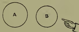
When a body is sufficiently strongly electrified and brought very near another body originally unelectrified, a spark will pass between them even before they are made to touch. If this second body is the finger or knuckle, the spark will be accompanied by a peculiar sensation called an electric shock. Now let us take such a highly electrified conductor A, and bring pretty near to it a second insulated conductor B, but not so near as to cause a spark to pass. If, then, the finger be brought near enough to B a shock will be felt, a spark will pass between B and the finger, although B was originally not electrified. Thus B has become electrified by being brought into the neighbourhood of A. This mode of electrification is called electrification by induction. As Faraday clearly pointed out, it 'has the character of a first, essential, and fundamental principle,' and its thorough comprehension is of prime importance.
As it is our purpose to regard the whole subject from the Faraday point of view, it will be convenient to define certain useful terms. The electric field is any region of air, glass, vulcanite, or other non-conducting substance surrounding or containing electrified bodies. In it and through it the electric forces act; hence it is convenient to call such insulating substances dielectrics, especially when attention is being drawn to the rôle they play as transmitters of electric action. To investigate the properties of an electric field it is generally necessary to bring into it a conductor, as in the experiment just described. In that experiment the induced electrical condition of B was studied by means of a physiological sensation, partly optical, partly muscular. A far better way, how-
* For the plan and distribution of the following article, see the epitome in the concluding paragraph. The word electric was coined in the 16th century by William Gilbert from the Gr. elektron, 'amber.' See AMBER.
ever, of studying the phenomena of induction is to make use of the fundamental laws of attraction and repulsion between electrified bodies, as they are mechanically applied in such instruments as the gold-leaf electroscope, Coulomb's torsion balance, Thomson's quadrant electrometer, &c.
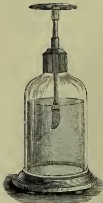
In the gold-leaf electroscope (invented by Bennet in 1787), two light strips of gold-leaf hang from the lower end of a metal rod, which passes vertically through an opening in the top of a glass bottle and expands above into a plate. If a piece of rubbed sealing-wax or other electrified body be brought near the plate, the gold leaves will repel each other and diverge. In other words, the conductor, consisting of the plate, rod, and gold leaves, has been introduced into an electric field, and has in consequence become electrified by induction. This is shown by the repulsion between the similarly electrified gold leaves. The nearer the electrified body is brought, the stronger is the electric field surrounding the electroscope, the wider do the gold leaves diverge. Here evidently the repulsion tends to lift the centre of gravity of each gold leaf, and is finally balanced by the action of gravity. A cylinder of wire gauze, placed just inside the glass case, improves the action of the instrument. The other two instruments mentioned above depend for their action upon the same general principle—viz. the equilibrium of a body under the action of the electrical and what, for distinction, might be called the material forces.
Coulomb's torsion balance is historically the first true electrometer—i.e. the first instrument whose indications were capable of quantitative interpretation. In it the force with which one small charged sphere is repelled by another similarly charged is balanced by the torsion of a wire, which acts as suspension to a horizontal insulating rod bearing the one sphere at one of its ends. By rotation of the upper end of the wire this sphere can be made to move in a horizontal circle; and at some point in the circumference of the circle the other sphere is fixed. If the spheres are charged, the rod bearing the movable sphere will take up a position of equilibrium under the combined action of the electrical force and the torsion of the suspension; and these, as regards their rotatory effect upon the rod, must be equal. But by the laws of elasticity, the force of torsion is proportional to the twist of the wire, and the twist itself is as easily measured as the distance between the spheres. Hence to the degree of accuracy to which the geometrical configuration of the system is known, the electric force can be calculated in terms of the elastic constants of the wire. In this way Coulomb proved, in 1785, that two small charged balls repelled each other with a force which diminished as the square of the distance increased.
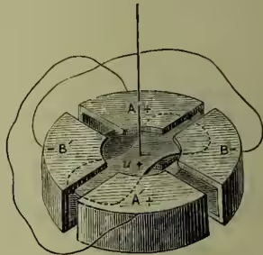
Sir William Thomson's quadrant electrometer is, in a certain sense, a development of Coulomb's torsion balance. Its many nice electrical and mechanical devices render it a peculiarly delicate and accurate instrument for measuring minute differences in electrification. Essentially it consists of four hollow brass quadrants, which when fitted close together form a squat hollow cylinder bounded above and below by parallel plane faces. For electrical purposes they must, however, be drawn a little apart, so that when looked at from above or from below they have the appearance as shown in the figure—viz. that of a circular disc with two mutually perpendicular diametral clefts. Each quadrant is insulated on its own glass support; but each is joined to its opposite by a wire, so that electrically they go in pairs. From one of each pair a vertical rod leads to the outside of the case in which the whole is inclosed.
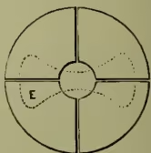
These rods are called the electrodes, and their function is to bring the pairs of quadrants into electrical connection with external bodies. The inside corner of the top and bottom of each quadrant is cut away, so that at the centre a small circular space is left concentric with the external cylindrical surface of the quadrants. In the hollow space inclosed by the quadrants a light charged body (E in fig. 3, u in fig. 4) of a convenient shape hangs, its axis of suspension passing up through the circular central space just mentioned. The light body can rotate about this vertical axis only, and its motion is controlled by the torsion of the suspension. If the four quadrants are all connected together, the suspension makes the light body hang so as to lie with its longer axis of symmetry parallel to one of the diametral clefts separating the quadrants. If, however, the pairs of quadrants are disconnected, and by connection with external bodies brought into different electric conditions, electrical forces will at once act upon the charged body and rotate it until they are balanced by the resisting torsion of the suspension.
Thus let the charged body u (fig. 4) be positively charged; and let the pairs of quadrants be charged differently, so that the ones marked AA' have a higher positive charge than the ones marked BB'. Then the charged body will move so as to come more within the quadrants BB'. If the relative electrifications of the pairs of quadrants is reversed, the charged body will move the other way. The motion is shown and measured by means of a beam of light reflected from a small mirror fixed to the vertical axis of suspension of the body and moving with it.
Henceforth we shall use the unqualified words electroscope and electrometer as meaning the gold-leaf electroscope and quadrant electrometer respectively.
We are now in a position to make an accurate study of the phenomena of induction. We shall suppose, when nothing is said to the contrary, that all our conductors are of one metal, say brass; that they are at the beginning of every experiment insulated and unelectrified; that the electroscope and electrometer quadrants are likewise unelectrified at the beginning of each experiment; and that the dielectric is air.
Experiment I.—Set a cylindrical brass vessel on the electroscope; and let down into it, without coming into contact with it, a positively charged conductor A. It is convenient to hang this charged ball at the end of a short silk thread from the lid of the vessel, the lid itself being lowered or raised by means of a silk thread. As soon as the ball is brought inside the vessel the gold leaves will diverge, as shown in fig. 5; and the vessel B, as regards outside objects, will behave as if positively electrified. Now touch B with the hand or with any non-insulating material connected to earth—in technical language, put the vessel to earth—and the gold leaves will fall together, and all appearance of electrification will be destroyed. Remove the earth connection so as to insulate B once more, and lift away the lid and the attached ball, care being taken to prevent A coming in contact with B. The gold leaves will again diverge, and the vessel
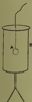
B will be found to be negatively electrified.
The nature of the charge on the vessel and gold leaves is indicated at once by the approach of an electrified body. If a piece of rubbed sealing-wax or any negatively charged body is brought near, the gold leaves, if negatively electrified, will diverge still more; if positively electrified, will tend to fall together.
In thus charging the vessel B negatively by induction, we have in no way diminished the original positive charge on A; and we may use this same charge an indefinite number of times in charging negatively other bodies like B. No doubt in each body so charged by induction we have a new-formed source of energy; but this has been derived, not from the energy spent in originally charging the ball, but from the energy spent in separating against their mutual attraction the positively charged ball and the negatively charged vessel.
Experiment II.—Begin again as in Experiment I, introducing the charged ball A into B, and putting B to earth, so that the gold leaves fall together. Now connect A with B. No effect will be observed on the electroscope, even though, as in the former experiment, A should be removed. Thus the charge on A has been completely destroyed; hence, there must have been on B, just before the contact was made, an equal but opposite charge. This is, in fact, the very charge which made its presence evident when, in Experiment I, the ball A was removed.
Thus, if a charged body A be completely surrounded by a closed vessel B, which is put to earth and then insulated, the charge induced on B is equal and opposite to the charge on A. To make this induced charge apparent we must remove A.
Experiment III.—Repeat Experiment I, and after having charged B negatively by induction, introduce A into another conductor C, initially without charge and insulated. If C is resting on a gold-leaf electroscope, the gold leaves will diverge with positive electrification as in the earlier stage of Experiment I. Bring now A into metallic connection with C. If C completely surrounds A, no change will be observed on the electroscope, although a spark may be heard at the instant the contact is made. The ball A, if removed without again coming in contact with C, will be found to have lost all its charge; and if B and C are brought into metallic connection, all appearance of electrification on them also will be destroyed. In other words, the negative charge induced on B has been quite destroyed by union with the positive charge transferred to C. These charges therefore must be equal and opposite. Thus, the charge originally on A has been wholly transferred to C.
We conclude, then, that when a conductor is electrified, its electrification resides wholly on the surface. Any portion of it removed from the inside will be found unelectrified if taken quite out of the influence of other electrified bodies.
This experiment, or one very similar to it, was first performed in 1772 by Henry Cavendish, who deduced from it by rigorous mathematical reasoning that 'electric attraction and repulsion must be inversely as the square of the distance.' He inclosed a metal globe within a hollow conducting shell which was built up of two hemispheres. The globe and shell were connected by a wire and charged. The globe was then disconnected from the shell, and immediately thereafter the hemispheres forming the shell were drawn asunder. The globe, now left exposed, was tested for electrification; and, to the degree of accuracy of the experiment, none was found.
Maxwell repeated the experiment in a much more delicate manner than was possible before the invention of the quadrant electrometer. During the charging of the shell and inclosed globe, these were connected by a short wire 'fastened to a small metal disc hinged to the shell, and acting as a lid to a small hole in it.' After the charging, this lid was lifted up by means of a silk thread, and the communication between the shell and the globe done away with. The shell was then discharged and kept connected to earth. Through the small hole in the shell a wire was led connecting the globe with one electrode of the quadrant electrometer. Not the slightest deflection could be observed.
It is impossible then to charge a body by placing it inside a charged conductor. In other words, there is no electric field within any region bounded by a conducting surface, however much that surface may itself be charged, unless there be within that region other insulated and independently charged bodies. It matters not what electrical phenomena may be taking place in the region outside such a conducting surface, such external electrical phenomena have absolutely no internal electrical effect; and vice versa, any purely internal electrical change can produce no external electric effect. In short, any closed conducting surface divides space into two regions, which are electrically independent the one of the other—i.e. so far as electrical action through either is concerned. This principle is taken advantage of in the construction of the quadrant electrometer, the essential internal arrangements of the instrument being inclosed as far as possible within a conducting vessel, the quadrants communicating with external space only by means of their electrodes.
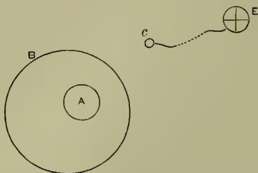
Experiment IV.—The conclusions just stated may be easily illustrated by use of the quadrant electrometer. Thus, as in Experiment I, let the positively charged body A be introduced into an insulated and initially unelectrified closed conductor B. Then, as we know, B becomes electrified, and the region round B becomes an electric field. The condition of this electric field may be studied by means of a small sphere C, joined by a long thin wire to one electrode—i.e. to one pair of quadrants—of the electrometer E. The other electrode is supposed to be kept connected to earth. Before A was introduced into B, the electrometer showed no sign of electrification. But as soon as A is introduced into B, C and its connected quadrants become electrified. The deflection produced on the electrometer will depend upon the position of C with regard to B and upon the original charge of A. It is quite independent, however, of the particular position of A, which may be moved about inside B without in any way affecting the deflection on the electrometer. A may even be brought into contact with B (as in Experiment III.) so as completely to lose its charge; and yet the electrification of C, as shown on the electrometer, is in no way altered—in other words, the electric field outside B is independent altogether of any purely internal changes which may take place inside B.
Suppose, now, that when A has been introduced into B, and a corresponding deflection obtained on the electrometer, B is put to earth. At once the electric field around B is destroyed, C and its connected quadrants recover their original un-electrified condition, and the electrometer gives zero deflection on its scale. Thus the charge on A is completely masked by being surrounded by a closed conductor put to earth.
Further, let B be insulated again and A removed with its charge—then, as we already know, B will be left negatively electrified. The region round B will again become an electric field, and C and its connected quadrants once more electrified. But the deflection on the electrometer, though equal to that first obtained, will be in the opposite direction, opposite because of the opposite character of B's electrification.
This experiment may be taken as an illustration of one of the most fundamental facts in electrostatics—viz. that the generation of so much positive electrification implies the generation of as much negative electrification. Here is a conductor B apparently without charge. Remove from it by any process a positive charge, and an equal negative charge is left behind. The same is true when bodies are electrified by friction, as may be proved by operating inside a closed insulated conductor joined to one electrode of the electrometer. The most energetic rubbing of the two bodies, and their subsequent separation, each in a highly electrified condition, produce no effect whatever on the electrometer—thus showing that their inductive effects on the inclosing conductor are equal and opposite—i.e. their charges are equal and opposite.
Experiment V.—To study in greater detail the properties of the electric field around a given charged conductor B, take two small insulated spheres and connect them by thin wires to the electrodes of the electrometer, each to one. Suppose these spheres to be at first in close contact at some part of the field; then, since the pairs of quadrants are in the same electrical condition, the electrometer will show zero deflection. Now gently separate the spheres, both insulated of course, and in general a deflection to the right or to the left will be obtained on the electrometer. By trial we may find the unique direction of separation which, for a given distance of separation, gives the maximum deflection. This will be to the right or to the left according to the relative position of the two spheres. It will be found, however, that a separation of the spheres in directions at right angles to this unique direction does not cause any deflection on the electrometer. It is far easier indeed to find these directions of separation for which there is no deflection than to find the direction of maximum deflection for a given separation. Suppose in fact that the one small sphere is fixed in position, and that the other, which we may call the exploring sphere, is moved away from contact with it in such a manner that the electrometer always shows zero deflection.
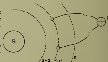
The centre of the exploring sphere will describe a curve, and can be made by successive trials to describe an infinity of curves, all lying on a certain surface which passes through the centre of the fixed sphere. We shall call this the surface S. Now with the exploring sphere lying anywhere on this surface, let the fixed sphere be shifted in towards B till the electrometer deflection is unity. Then shift the exploring sphere correspondingly until the deflection is brought back to zero again, and proceed as in the first position to trace out a second surface, which we shall call S + 1, and which will pass through the centre of the fixed sphere in its second position. Shift the fixed sphere once more till unit deflection is obtained, follow up with the exploring sphere, and trace out the third surface S + 2. In this way, step by step, the electric field may be supposed to be mapped out by a series of surfaces, differing in value by unity as measured on the electrometer scale. We may pass out to the surfaces S - 1, S - 2, S - 3, &c., as well as in to the surfaces S + 1, S + 2, S + 3, &c. These surfaces are all closed, and cannot cut each other. For suppose two did cut each other; then, by putting the fixed sphere in the supposed line of intersection, we could move the exploring sphere from the position S to the position S + 1, and produce no change on the electrometer; which is a manifest absurdity, as S + 1 is defined in terms of S and a change. If the electrodes of the electrometer terminate on any one of these surfaces there is no deflection; if they terminate on different surfaces the deflection is the difference of the name-values of the surfaces. Evidently the conductor B is such a surface, for if the electrodes terminate on it, all the quadrants, being in metallic connection, will be in the same electrical condition, and the electrometer will show no deflection.
The surfaces we have just described are called equipotential surfaces, the term potential having in electricity much the same import as temperature has in heat or pressure in hydrodynamics. When a channel exists between two masses of fluid at different pressures, fluid will flow from where the pressure is higher to where it is lower. Similarly if we have two charged conductors whose electrical conditions as tested by electroscope or electrometer become changed after they have been connected by a wire and disconnected again, these two conductors are said to have been at first at different potentials. If they had been connected to the electrodes of the electrometer, each to one, the electrometer would have shown a deflection; and this deflection would have been a measure of the difference of potential. If the difference of potential is great, then the contact of the two conductors is evidenced by an obvious electrical discharge in the form of a visible audible spark.
If we directed our attention to conductors only, we should not find any special advantage in using the phrase 'difference of potential' instead of 'differently electrified;' but when we follow Faraday in regarding the dielectric as of at least equal importance as the conductor, the conception of the potential is found to be one of peculiar value. Thus any conductor or any system of connected conductors must have all points at the same potential; whereas, in a dielectric, the potential may vary from point to point, and indeed must vary if the dielectric is separating two conductors at different potentials.
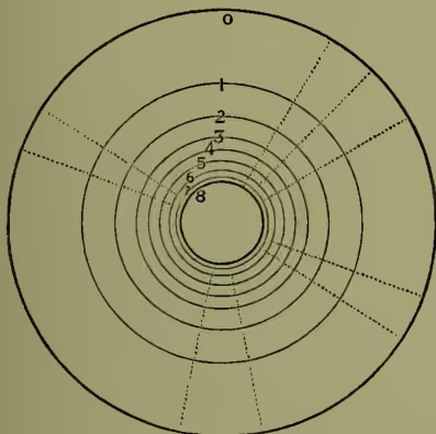
Within such a dielectric we may suppose traced out, after the manner of the last experiment, a series of equipotential surfaces. To fix our ideas, let the one conductor be completely inclosed within the other—say, a spherical globe within a concentric spherical shell—and let this outer shell be put to earth, and let us call its potential zero. Then we know by Experiments II. and IV. that the electric field exists only in the region between the shell and the globe, which we shall suppose to be at a high potential . The symmetry of the system requires that the other equipotential surfaces will all be spheres concentric with the globe and shell. Now we may compare this electrical system of globe, shell, and intermediate equipotential surfaces to a square of the distance from the centre and acts outwards.
We have assumed in the above discussion that the successive equipotential surfaces, experimentally determined by means of the quadrant electrometer, are really such that the work done in carrying a given small charge over the interval separating any two contiguous surfaces is the same. It is usual in treatises on the subject to begin with the dynamical definition of the potential at a point as the work done in carrying a unit of positive electricity from infinity to that point. It is then shown that the quadrant electrometer is an instrument so constructed as to fit in to this definition.
Assuming then that our equipotential surfaces have the property just mentioned, we are in a position to study the energy relations of the electric field.
Coulomb established by experiment that the force of repulsion between two similarly charged bodies was directly as the product of the charges. Hence, as the charge of the globe inclosed in the shell is increased, the electric forces in the field increase in the same proportion. Hence the work done in carrying a given charge from the shell to the globe against the electric forces increases in the same ratio. In other words, the number of equipotential surfaces in the field grows uniformly with the charge. If the potential of the globe is , we may write the charge , being a constant so long as the geometrical dimensions of the system remain unchanged. Since the shell is always kept connected to earth—i.e. at zero potential, there is a charge distributed over the inside of the shell. To add a small extra charge to the globe may be regarded as equivalent to taking this small charge from the shell, carrying it across the dielectric, and distributing it over the globe. The work done in effecting this is evidently proportional to the charge taken and to the number of equipotential surfaces crossed. But as the extra charge is added, let us suppose, at a steady rate, the potential of the globe is increased at a proportional steady rate. Hence the whole work done in adding a given charge is equal to the product of the charge and the mean potential of the globe during the operation. Thus, in charging the globe from zero potential to potential , we do an amount of work equal to half the product of the final potential into the final charge —in symbols or or , where is the charge, and the constant which depends on the geometrical dimensions of the system.
We have already seen that positive and negative electrifications always co-exist—that it is impossible to generate so much positive charge without at the same time generating as much negative charge. Faraday took implicit account of this truth in his conception of lines of electric force traversing the dielectric. Since no work is done against the electric forces in passing along an equipotential surface, we readily see that the electric force at any point is perpendicular to the equipotential surface there. This direction is, in fact, the unique direction of separation of the two terminal spheres in Experiment V., which, for a given distance of separation, gave the maximum deflection. If, starting from any point, we move always perpendicular to the equipotential surface through which we are for the moment passing, we shall describe a curve which at every point of it is tangential to the direction of the electric force there. Such a curve is called a Line of Force. Take any small area on an equipotential surface, and draw lines of force through its perimeter. These lines of force will form a so-called Tube of Force, whose section in general will vary as we pass along it. Following this tube of force backwards to its source, we shall finally come to a system of Contour (q.v.) lines representing a hill with a flat top rising up from the sea-level—the successive equipotential surfaces in the electrical system corresponding to successive equal-level lines in the geographical system. If the substance of the hill were to become fluid, the whole would be reduced to the sea-level, and the contour lines would be effaced. So, if the dielectric were to become conducting, the equal and opposite charges (see Experiments II. and IV.) on the globe and shell would combine and destroy each other, and the electric field with its imaginary equipotential surfaces would cease to exist. Again, to carry one pound of matter from the sea-level up to the top of the hill requires so much work to be done against gravity (see ENERGY), and this amount of work is proportional to the height lifted through—i.e. to the number of contours crossed. So, in the electrical system, to carry a small positive charge from the shell to the globe will require so much work to be done against the electrical forces, and this amount of work will be proportional to the number of equipotential surfaces crossed. Further, exactly as the pound of matter taken to the top of the hill will add to the height of the hill, so will the addition of this small extra charge to the globe increase its potential. We must not, however, push the analogy too far, since in the one case the force of gravity overcomes is constant and acts downwards, whereas in the other the electric force varies inversely as the positively charged conductor; and following it forwards we shall ultimately come to a negatively charged conductor. Every such tube of force has, in short, two ends. It springs perpendicularly from a positively charged area, and terminates, also perpendicularly, on a negatively charged area. According to Faraday's view, and to the view now generally accepted, it is along these tubes of force that electric induction takes place; so that the negative charge on the terminal area is exactly equal to the positive charge on the area from which the tube springs.
In the symmetrical system of globe and shell the lines of force are obviously straight radial lines, the tubes of force portions of cones terminated by the spherical surfaces. Some of them are indicated by the dotted lines in fig. 8. If we take each tube as springing from an area bearing unit charge, then there will be in the region as many tubes of force as there are units of charge—i.e. there will be unit tubes of force. These unit tubes of force with the equipotential surfaces will cut up the dielectric into imaginary cells, each of which may be regarded as containing half a unit of energy. In fact, exactly as a stretched piece of india-rubber contains in every element of it so much energy in virtue of the elastic stresses acting throughout it, so we are to regard an electric field as a kind of strain existing in the dielectric, so that in every element of the dielectric so much electrical energy is stored up in virtue of the electric stresses. Every complete unit tube of force contains units of energy; and between any two complete equipotential surfaces differing by unity there are units of energy stored up. Clearly the electric strain will be greatest where the unit tubes of force are narrowest and where the equipotential surfaces are closest.
Suppose, now, that in the region between the globe and shell an insulated conductor originally unelectrified is introduced; or, what comes to the same thing, suppose a marked off region in the electric field to become conducting, this region will at once be reduced throughout to the same potential, and its surface will form part of an equipotential surface. But, since originally the potential in this region fell steadily as we passed outwards from the globe, a transference of charge must have taken place also outwards in order that the potential should become equalised throughout. The introduced conductor in fact acts as a channel along which electrification is transferred; so that, if tested, the end facing the globe will be found negatively electrified, and the farther end positively electrified.
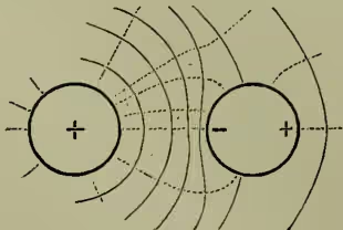
Now it is evident that the introduction of this conductor into the field has very much changed the configuration of the equipotential surfaces in its vicinity, the new configuration being something like what is indicated in the diagram (fig. 9). As a consequence, the tubes of force, which are necessarily perpendicular to the equipotential surfaces, must also suffer a corresponding change of configuration. A certain number, springing from the globe, will fall perpendicularly on the nearer part of the introduced conductor, while from the farther part an equal number of tubes of force will spring and continue outwards to the shell. Where the tube ends on a conducting surface, there we find unit negative charge; and where it springs from a conducting surface, there we find unit positive charge. Thus, by consideration of the equipotential surfaces and tubes of force, we are led to a conclusion in strict accordance with the experimental truth that an uncharged conductor brought near a charged conductor becomes electrified by induction, so that the nearer end shows an opposite charge, and the farther end shows a similar charge, to that which exists on the charged conductor.
Generally speaking, the effect of the presence of the introduced conductor is to crush the tubes of force in the neighbourhood closer together, and therefore (since this number remains constant) to compel an expansion of them elsewhere. The terminals of the tubes on the globe will obey the same tendency towards concentration and expansion. In other words, the charge , at first distributed uniformly over the globe, becomes redistributed and tends to accumulate on the side facing the conductor. The nearer the conductor and globe are brought, the greater will this tendency be; and at last, when they are near enough, the dielectric is unable to sustain the high electric tension along the ever-shrinking tube of force. It yields, a more or less sudden transference of charge takes place in the form usually of a spark, the potentials of the globe and conductor are practically equalised, and the tubes of force between them are annihilated. This is the phenomenon which is exhibited on a large scale in every lightning-flash, and on a small scale in every spark between electrified bodies.
Suppose, however, that before this catastrophe has taken place, the conductor is joined by a wire to the surrounding shell, and consequently brought to zero potential. All those equipotential surfaces which at first enclosed the conductor—i.e. lay between it and the inclosing shell, will be shifted so as to lie between it and the globe. The tubes of force will shift correspondingly; and as no tube can now pass from the conductor to the shell, none will spring from it. Hence the charge on the conductor will be wholly negative. Now experiment shows that when the conductor is brought to zero potential in the way just described, a spark always passes at the instant the connection is made. This spark means so much energy in the form of light, sound, and heat, and must therefore mean a disappearance of energy in some other form. This cannot be other than electrical energy. Consequently the number of unit cells in the dielectric must be diminished. But the charge on has not changed, so that the number of tubes of force is exactly as before. The change must therefore be in the number of equipotential surfaces; and since the shell and the conductor are at zero potential, the diminution must take place in the potential of . Thus we see that the potential of a positively charged body is diminished if a conductor at zero potential is brought near it.
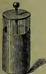
This result leads naturally to the discussion of capacity. The capacity of a conductor is measured by the ratio of its charge to its potential. Hence if, as in the experiment just described, we have a diminution of potential with constant charge, this is equivalent to an increase of capacity. The greater the capacity of a conductor, the greater the charge it can hold at a given potential. Hence if a number of conductors are at the same potential, the charges must be distributed amongst them directly as the capacities. The experiment just described shows how we may arrange matters so as greatly to increase the capacity of a given conductor. It is sufficient to have close to it another conductor at zero potential. Such an arrangement of conductors is called an accumulator or condenser; and the most familiar form of accumulator used in electrostatic experiments is the Leyden jar, so called from the city where, in 1745, its properties were accidentally discovered by Cunæus. About the same time, possibly a month or two earlier, almost exactly the same discovery was made by Kleist at Kammin in Pomerania. In its modern form, a Leyden jar is a cylindrical glass bottle, lined inside and outside with metal foil up to within a short distance from the top. A brass rod connected below with the inside coating passes upward through the cork or stopper, and terminates generally in a ball or knob. A Leyden jar then consists essentially of two conductors, the one almost completely inclosed in the other, and separated from it only by the thickness of the dielectric. If either conductor is put to earth, and the other insulated and charged, an opposite and nearly equal charge is induced on the former. If we could completely surround the one conductor by the other, the induced charge would, as we have seen, be exactly equal but opposite to the inducing charge. Leyden jars are indispensable for carrying out illustrative experiments in electricity. When used in combination, they are said to form an electric battery.
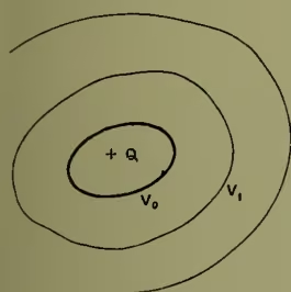
The essential nature of the mode of action of an accumulator or condenser may be illustrated as follows: Take any charged conductor with its associated electric field. Let be its charge, its potential, so that is the measure of the electric energy stored up in the field. Having fixed our attention upon any equipotential surface inclosing the conductor, let us suppose this surface to become conducting. There will be no transference of charge over this surface, because it is from the very beginning an equipotential surface. There will be no change of the electric field either inside or outside the surface ; but these two regions will now be separated by a conducting surface. So far as the outside region is concerned, we may regard the charge as distributed over a conductor co-extensive with the conducting surface (see Experiments III. and IV.), and may quite disregard the existence of the original conductor at potential . The electrical energy stored up in this outside region is therefore a . Let us now connect this new-formed conductor to earth so as to reduce it to zero potential.
By so doing, we discharge the conductor, completely destroying the electric field outside of it and the units of electric energy stored up in it. This therefore is energy lost to the original system; and the energy stored up in the dielectric separating the two conductors becomes a . Now, since the inclosing conductor has been reduced to zero potential, the quantity must represent the new potential of the inclosed conductor.
In short, the bringing of the inclosing conductor to zero potential, being a purely external electrical change, has in no way altered the configuration of the equipotential surfaces and tubes of force inside; it has simply reduced the potential values throughout by the same amount—viz. the potential of the inclosing conductor before it was put to earth. The potential of the inclosed conductor has fallen from to ; and hence, as the charge has remained unchanged, the capacity has increased in the ratio . Thus, with either conductor fixed in size, the capacity of the system grows greater and greater as the thickness of the separating dielectric is diminished. If, as in almost all practical cases, the dielectric is very thin compared to the size of the conductors, we may assume that the successive equipotential surfaces come at sensibly equal intervals, so that the surface halfway between the conducting surfaces will have approximately a potential value half-way between the potentials of the conductors. Thus it is easily seen that for a condenser built up of closely opposed surfaces, whether plates or cylinders, separated by a given dielectric, the capacity varies inversely as the thickness of the dielectric.
Take, for example, two concentric spheres, one slightly larger than the other, and let the inner one have a charge , and the outer one be at zero potential. The negative charge on the outer sphere will, by a well-known proposition in attractions, exert no electric force throughout its interior. Hence, if is the mean of the radii of the spheres, we may write as a very approximate value for the mean electric force acting in the region separating the spheres. If is the small distance between the two surfaces, the work done in carrying unit charge from the outer to the inner surface is , the product of the distance into the mean force. This therefore measures the difference of potential of the two spheres, so that is the capacity. Now, we shall suppose that is kept constant, and that is made to grow indefinitely; then if we write , the quantity will be the charge on unit area of the inner surface. Hence, ultimately, when the concentric spheres become two parallel planes, the difference of potential between them is measured by the quantity , where is the charge on unit surface of the one plane, the charge on the opposing surface of the other, the distance between the planes, and the ratio of the circumference of a circle to its diameter. The force is measured by the rate at which the potential changes, in this case simply , and is therefore the same not only at every point between the planes, but also for all values of .
Now we may calculate the electric force very close to any charged surface on the supposition that the contiguous surface element is part of an infinite plane having the same charge per unit area—in other words, the same surface density. By surface density at any point of a charged conductor we mean the limit of the ratio of the charge on a small element containing the point to the area of the element, as the element is taken smaller and smaller. Such is the quantity just discussed. Thus the electric force just outside a charged conductor is equal to , where is the surface density at the contiguous point of the conductor. It is a repulsion when is positive, an attraction when is negative.
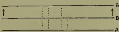
We may use the result just obtained for finding the force acting on an element of the charged surface itself. Consider the two parallel planes at distance and difference of potential , being as above the charge on unit area. Hence the energy stored up in a tube of force stretching from the unit area on B to that on A is . Now, with A at zero potential, let B be moved away to double its original distance from A—i.e. through a distance to B'. If the charge on unit area remains constant, the energy stored up in the corresponding tube of force has become simply doubled, so that there has been an increase in electrical energy represented by the quantity . But this must be equivalent to the work done in removing the charge through the distance against the electrical force; hence, the value of this force estimated per unit charge must be . Thus the force per unit charge acting on the surface is just half the electric force acting on unit charge at a point in the field just outside the surface. Otherwise, if is the electric force at a point just outside a charged surface, is the measure of the surface density at the contiguous surface element, and is the force per unit charge acting on the surface.
The importance of this result is that it gives us a simple method of measuring electric force in terms of weight. It is the principle of Thomson's absolute electrometer, which is essentially two parallel plates at different potentials, one of which is made so that a small area at its centre is movable under the action of the electrical force. Where this small area is, the electrical system does not differ appreciably from what would be the case if the plates were
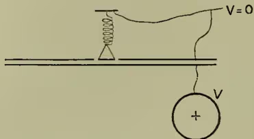
We may suppose the small area suspended by a spiral spring, and that, when the plates are at the same potential, grammes must be laid on the small area to bring it so that its lower surface is flush with the lower surface of the rest of the upper plate. Let the weight be removed, and the lower plate be put in connection with the conductor whose potential is to be measured. Now raise or lower this plate until the small area, which with the rest of the upper plate is kept at zero potential, is brought again to be flush with the upper plate. Then we know that the suspension is stretched by a force equal to the weight of grammes. Now, if the potential of the lower plate is , and the distance between the opposed surfaces, is the electric force in the region between the surfaces, and the measure of the charge on unit area. Hence the force acting on unit area is ; and finally, if be the area of the small suspended portion, we have
In this equation , , are all known, hence is measured in terms of definite units. In the universally adopted system of scientific dynamic units, we must multiply by the quantity , which measures the number of units of force equivalent to the weight of one gramme. Then we find
As a special case, suppose that is 50 grammes, and one square centimetre; then, with , we find , and 88.3 units of charge on the unit area. The unit of charge here referred to is that quantity which when placed at 1 centimetre from an equal quantity will repel it with a force of 1 dyne—i.e. a force which, acting on 1 gramme for 1 second, will increase its velocity by 1 centimetre per second. This quantity is called the electrostatic unit of quantity; and the electrostatic unit of potential is the potential of a sphere of radius 1 centimetre, and charged with this unit quantity.
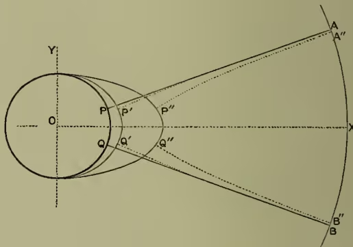
Generally speaking, except in such obviously symmetrical cases as concentric spheres, infinite co-axial right cylinders, and infinite planes, the surface density will vary from point to point of a conductor, and where it is numerically greatest there also will the electric force close to the surface be greatest. In the case of a simple elongated conductor, the surface density is greatest at the ends. This may be proved very easily by experiment, by, for example, measuring the charge which a very small disc carries away after contact with the conductor. The following reasoning will lead to the same conclusion. Take a uniformly charged sphere in wide space, so that the equipotential surfaces are concentric spheres, and the tubes of force radial cones. If this sphere, by appropriate expansion at right angles to a given diameter, becomes changed into an oblate spheroid, what is the nature of the accompanying change in the surrounding electric field? Let be the given diameter, and consider a tube of force symmetrical about any axis perpendicular to . Let represent this tube of force for the sphere. Along this tube induction takes place, so that the positive charge on would induce an equal negative charge on , if the equipotential surface, of which is a part, were to become a conducting surface. We may express this by saying that the electric displacement across any section of a tube of force is equal to the charge on , the area from which the tube springs. Now let the sphere change form in the manner described, but to such a small extent that no appreciable change is produced at the distance . The electric displacement across is therefore the same as before; and, if we follow back the tube of force to the conductor, we shall find the corresponding charge distributed over the area from which the tube springs. But, the conductor being itself an equipotential surface, the lines of force must meet it perpendicularly. Hence, near the deformed conductor, each line of force will suffer a displacement as shown in the figure, where represents the new position of what was originally the line of force . Similarly the line will bend inwards to the position . In other words, the tube of force as it springs from the spheroidal surface lies wholly within the tube of equal strength which sprang at first from the spherical area . The unit tubes of force which compose the tube which passes through are, therefore, more concentrated in the region than they were in the region . Hence, the remaining unit tubes of force which spring from the rest of the conducting surface are, taken as a whole, more expanded over the rest of the spheroid than they were over the rest of the sphere. Thus, the average density over is greater than the average density over the rest of the spheroid. Now we may suppose this almost spherical spheroid to become elongated little by little. At every step a readjustment of the lines of force will take place, until at length for a pronounced ellipticity they come into the positions , . At a far enough distance, however, these lines of force will be indistinguishable from the original positions , . Hence, the electric displacement across a far-away section of the tube being as before, the charge on will be the same as that originally borne by . Thus, the more elongated the ellipsoid becomes, the greater is the relative concentration of charge towards the ends. It may be easily shown that the lines of force springing from are branches of a hyperbola confocal with the spheroid, and having , for asymptotes.
This accumulation of electric charge towards the ends of a pointed conductor is well exemplified in the lightning-conductor, which is simply a very elongated piece of metal in contact with the earth. A charged body of air, such as we have accompanying a thunder-cloud, passes near it. The tubes of inductive force are at once concentrated on the elongated conductor; the electric force at the point becomes so intense that the air can no longer act as a perfect insulator; electrical discharge takes place along these very tense tubes of force; and in a more or less gradual manner the cloud is robbed of its charge, and the evil effects of a sudden lightning-flash minimised. On the same principle, electric discharge through air is facilitated by the use of pointed conductors, such as the combs which are so important a detail in machines for generating electricity by means of friction.
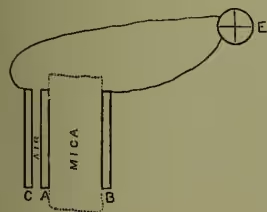
We have seen that the capacity of a condenser depends upon the distance between the surfaces or plates which compose it; it also, however, depends very materially on the nature of the dielectric. Suppose, for example, that we have a series of condensers, made of the same conducting material, and all exactly equal as regards their geometrical and space relations, but all differing as regards the dielectric which separates their plates. Thus let one have air as its dielectric, another plate-glass, another paraffin, another mica, and so on. Let them now all be brought to the same potential, then disconnected and tested as to charge. The charges will be found to be all different—being, in the four cases we have mentioned, approximately proportional to the numbers 1, 6, 2, 6.6. These four numbers are the values of what is termed the specific inductive capacity of air, glass, paraffin, and mica. Thus by merely inserting a plate of mica between two plates of an air condenser, we increase the capacity by as much as if we had approached the plates in air through a distance equal to .85 () of the thickness of the mica. Otherwise, let there be two metal plates, , , separated by a thin plate of mica, and on the other side of let a third equal-sized plate be so adjusted that when is charged, the potentials of and shall be equal. This can be readily done by severally connecting and to the electrodes of the electrometer, as indicated in the figure. Then it will be found necessary to adjust so that the distance between and is about 6.6 times the distance between and .
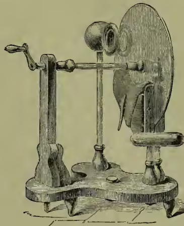
We may now fitly consider the principles of action of the various machines that are used for generating electricity. The rubbed pieces of resin, sulphur, glass, &c. were gradually succeeded by spheres, cylinders, and circular plates of these materials, which, as they revolved against prepared rubbers, were kept in a constant state of electrification. Any insulated conductor brought near enough to a portion of such a cylinder or plate at a distance from the rubber will become charged, the dielectric strength of the air breaking down exactly as in the case of the lightning-conductor and the thunder-cloud. Such is the action of the ordinary frictional machine; obviously the conductor acquires a charge similar to that on the revolving cylinder or plate. The opposite charge on the rubber may be transferred to another conductor, which is usually put to earth. Le Roy's or Winter's plate machine is shown in the diagram (fig. 16).
Essentially different in its action is the electrophorus, invented by Volta in 1771. In its most improved modern form it consists of two plates, one of metal, and the other of resin, vulcanite, or ebonite backed with metal. Insulating handles can be screwed on to the backs of the plates; and one plate at least must be so insulated. The surface of the ebonite is first electrified by friction, and the metal plate is brought into close contact with it. The metal plate, from its greater proximity to the negatively charged surface of the ebonite, will be at a lower potential than the metal back to the ebonite. If these are then brought into contact—conveniently effected by means of a metal pin passing through the ebonite—a transference of charge will take place, so that the metal plate when lifted away will be found positively charged, while the metal back is left negatively charged. In this machine, the original negative electrification on the rubbed surface of the solid dielectric is used again and again, in accordance with the principles of electrostatic induction and convection, to produce a practically unlimited amount of either kind of electrification.
In Nicholson's 'revolving doubler' we have the parent form of a number of rotatory machines which, like the electrophorus, depend for their action upon induction and convection. They make direct use of the principle of 'doubling' discovered by Bennet, by which the difference of potential between two conductors is indefinitely increased. Thomson's replenisher, which is an important part of the quadrant electrometer in its perfected form, is perhaps the simplest and most compact of these machines. In it, a turning vertical shaft of ebonite bears, at the ends of a horizontal cross-piece of ebonite, two metal pieces called carriers (cc in the diagram, which represents a horizontal section). These carriers rotate in the region between two insulated metal inductors (a, b) in the form of cylindrical segments. When the carriers are in position AB, they come into momentary contact with delicate springs attached to the neighbouring inductors; and when they are in position CD, they come into momentary contact with delicate springs connected by a metallic are which is quite insulated from the inductors.
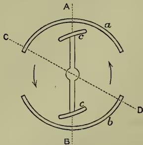
Suppose to be at a higher potential than , and consider what takes place as rotates counter-clockwise, as shown by the arrows in the figure. In the position AB, the carriers are well surrounded by the metal shields, and will part with nearly all the charge that may chance to be upon them. Just before they come into contact with the springs in position CD, the two carriers are at different potentials. Hence at the moment of contact with the connecting springs, a transference of charge will take place from the carrier near to the carrier near . The former will thus acquire a negative charge, and will move on till it comes within the inductor , to which it will give up nearly all its negative charge; while the latter will simultaneously give up nearly all its positive charge to . Thus every complete revolution each carrier becomes once negatively charged and once positively charged, giving up its negative charge to the one inductor, and its positive charge to the other. The inductors therefore steadily increase in positive and negative charges, or in other words, their difference of potential steadily grows. If the carriers are rotated clockwise, the opposite effect will take place, acquiring so much negative charge every revolution, and so much positive charge. In the electrometer, is in connection with the charged body, which is suspended inside the quadrants. A very elegant contrivance enables the operator at once to tell if this body is charged to its normal condition. If it is undercharged, a few turns of the replenisher in the proper direction will bring the potential up to its proper magnitude; if it is overcharged, a few turns in the reverse direction will bring the potential down to its required value.
The same principles of induction and convection are made use of in the so-called influence machines, which in recent years have quite eclipsed the older frictional machine. These are generally known by the name of their inventors, such as Töpler, Holtz, Bertsch, Voss, and Wimshurst. Of these, the Wimshurst is the latest, and apparently the most satisfactory. It consists of two circular glass plates, mounted on a common spindle, and capable of rotation in opposite directions with equal speeds. Each plate carries twelve or sixteen strips of thin sheet-metal, fixed radially at regular intervals apart. These strips lie on the outside of the closely opposed glass plates. At the extremities of the horizontal diameter of the plates the main conductors are placed, insulated on glass or vulcanite pillars. Horizontal arms with the usual combs project inwards, embracing both plates as far as the inner ends of the metal strips. In front is fixed a diagonal conductor, called a 'neutralising rod;' and a similar rod is fixed behind at right angles to the one in front. These neutralising rods terminate at both ends in a small metal brush, which touches the metal strips or carriers as they pass. By this contact of brushes and strips, every strip on either plate is, very soon after it has passed under the collecting combs, brought into metallic connection for a moment with the strip diametrically opposite it on the same plate.
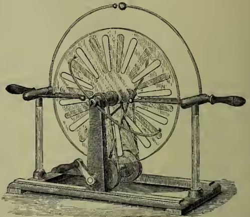
Suppose the principal conductors to be at different potentials, then—exactly as in Thomson's replenisher—the carriers as they leave the brushes of the neutralising rod will acquire a charge, negative or positive, according as they are nearer the positively or negatively charged main conductor. But, evidently, each carrier on the one plate will act as inductor to the carriers on the other plate; and a moment's consideration will show that this inductive action will everywhere accentuate the inductive action of the main conductors. Thus the positive conductor is being fed by the positive charges brought by the strips on the upper half of the one plate and on the lower half of the other; while the negative conductor is being fed by the negative charges brought by the strips on the lower half of the one plate and the upper half of the other. The main conductors are provided with arms, which reach out towards each other, and between whose terminal knobs discharge takes place. Sparks, 3 to 5 inches in length, can easily be obtained with this machine.
So far we have confined our attention almost entirely to electrostatic phenomena—i.e. to phenomena connected with the existence of a steady electric strain in dielectrics. When compelled to deal with the transference of so-called charge from conductor to conductor, we had regard rather to the initial and final equilibrium conditions than to the intermediate condition of change. This condition of change, however, has clearly very important energy relations. In all cases of electrical discharge there is, in the language of Faraday, a concentration of the lines of force in a certain region of the dielectric, until that becomes, as it were, overstrained, and yields with a more or less evident appearance of part of the energy of strain in the form of light, sound, and heat. The particular manner of transformation into these commoner forms of energy depends on a variety of circumstances, such as the pressure and temperature of the dielectric, the form and relative size of the conductors, and so on. Even if there be no such energy transformations apparent to our senses, it can be shown that any equalisation of potential without increase of total charge necessarily results in a loss of electric energy to the system.
Thus, let there be two insulated conductors of capacities and , originally at different potentials. If they are brought to the same potential by being connected by a thin wire of comparatively insignificant capacity, the original charges on the conductors will become redistributed, and the final charges will be and . Whatever charge the one conductor has lost, the other has gained. Hence we may write the original charges as , , where is the charge which has been transferred from to . Now the energy of any charged conductor is measured by half the charge into the potential or half the square of the charge divided by the capacity. Thus the final energy, after equalisation of potentials, is :
while the initial energy was
Hence, since is always positive, we see that the initial energy is necessarily greater than the final energy. The loss of energy is represented by a quantity which is proportional to the square of the charge that has been transferred. If we look more closely into the significance of this quantity, we see that it represents the electrical energy of the system of two conductors of capacities and when they are charged each with units of either positive or negative electricity; or, more particularly, it represents the work which must be done in carrying units from the one to the other. This is an example of the general principle that the work done by the electric field in compelling a transference or flow of electricity from one region to another is exactly equal to the work which must be done against the electrical forces in carrying an equal quantity of electricity back again.
It is convenient, especially when the flow of electricity is the subject of consideration, to use the term Electromotive Force instead of Difference of Potential. We may suppose it measured by means of the quadrant electrometer. Thus if the regions and are connected severally to the electrodes of the electrometer, the deflection will measure the electromotive force acting along any conducting channel which may be supposed to bring and into communication. The flow of electricity which this electromotive force compels will tend to bring and to the same potential; and in the ultimate vanishing of the deflection on the electrometer we have the evidence of such a flow having taken place. But we may suppose that, by some means, notwithstanding the conducting channel between and , their difference of potential is sustained, so that the electromotive force acting along the channel is kept constant. Then the electrometer will show a steady deflection; while at the same time a steady flow of electricity will take place along the channel. This flow, whose existence is indicated only indirectly by the electrometer, must be measured by some one of its direct effects.
These effects are conveniently grouped into physiological, thermal, chemical, and magnetic.
The electric 'shock,' experienced when the experimenter uses himself as a discharging conductor, is a familiar example of the physiological effect of an electric current. The electric discharge causes a muscular contraction. In 1790 Galvani observed that the limb of a frog, when touched simultaneously by two different metals in contact, was convulsed exactly as if subjected to an electric shock; and Volta, following up this observation, discovered in 1800 a new source of electromotive force which could sustain an electric current through a conductor for a lengthened period of time. From this dates the development of Galvanic or Voltaic electricity, or, as it is now more commonly called, current electricity. The electric shock, however, depends upon variations in the amount of flow; a steady current produces no shock, except when it is beginning or ending.
In the electric spark there are of course thermal effects; and generally, since, as we have seen, a transference of charge or flow of electricity means a loss of electric energy, an evolution of heat is a necessary consequence.
Towards the close of last century the decomposition of water by an electric discharge was observed by Van Troostwijk and Deiman; while with Volta's electrical discoveries a new era in chemistry as well as in electricity was inaugurated.
None of these effects, however, give a ready method for measuring a steady electric current—i.e. the amount of electricity which is transferred across any section of the conductor in a second, or in any other chosen unit of time. For this we must go to the fourth group—viz. the magnetic effects of currents. This branch of the subject, which includes electro-magnetism, and as a consequence much of electro-dynamics, dates from 1820, when Oersted of Copenhagen discovered the action of a current upon a magnet suspended near it. As a matter of history, the discovery was made by means of voltaic electricity; but that there was some close relation between magnetism and electricity had long been recognised by experimentalists. Lightning had been known to destroy and even reverse the polarity of ships' compasses. Steel and iron had been magnetised by discharging electricity through them; but the effects of such sudden discharges were extremely capricious, and quite baffled all attempts to co-ordinate them. We may, however, by discharging a Leyden jar through a carefully insulated wire suitably coiled round a magnet, show that at the instant of discharge the magnet is displaced.
The broad fact established by Oersted was that every electric current tends to make a magnet set itself perpendicular to the direction of the current. To make the effect specially apparent, the wire conveying the current should be coiled again and again round the region in which the magnet is placed. The same current is thus brought again and again into the vicinity of the magnet, and has a proportionately greater effect. An instrument consisting in this way of a coil of wire surrounding a magnet, free to rotate in some plane passing through the axis of the coil, is called a galvanometer. The coiled wire must be covered with gutta-percha, silk, or cotton thread, so that the contiguous coils may be insulated from each other; and, for ordinary purposes, the plane of the coil should contain the magnet when no current is flowing. We may suppose the magnet to be suspended horizontally under the influence of the earth's magnetic field; then the plane of the coil should contain the magnetic meridian (see MAGNETISM). The ends of the coiled wire are called the terminals of the galvanometer. When they are connected to conductors at different potentials, a current will flow round the coil of wire, and will indicate its presence by compelling the magnet to move out of its normal position of equilibrium. The tendency of the current in the coil is to make the magnet turn itself at right angles to the plane of the coil—i.e. to set itself along the axis of the coil, magnetic east and west. But this is resisted by the steady action of the earth's magnetic field. The result is a compromise, and the magnet is deflected from its normal position in the magnetic meridian through an angle which depends on the relative values of the current and the earth's magnetic force. Since the latter is practically constant, the angle of deflection will depend on the value of the current, being greater for the greater current. It is not our purpose under this heading to enter into the magnetic relations of currents. For that we refer to MAGNETISM. It is sufficient at present to know that in the galvanometer we have an instrument which can measure current, exactly as in the electrometer we have an instrument which can measure difference of potential or electromotive force.
In discussing the equalisation of potential in electrostatics, we purposely confined our attention to one metal only. The reason was simply because, in general, two different metals, or in fact any two different conductors, can never when in direct contact be at the same potential. The discovery of this fact we owe to Volta. Take, for instance, any four conductors BAXB, put them in series as in the figure, and connect the terminal members, which are of the same material, to the electrometer. According to the character of the conductors AXB, there may be, or there may not be, a deflection on the electrometer.
(1) If there is no deflection, the two B's are at the same potential; and yet, according to Volta's discovery, the three different substances are at different potentials. This may be shown at once by breaking the chain at any of the separating surfaces, when a deflection on the electrometer will be observed. During this act of separation, the separating surfaces, one of which must of course be kept insulated, act like a condenser with a constant charge, the difference of potential changing because the capacity is changing. The reason why the B's are at the same potential is that, whatever be the differences of potential between B and A and between A and X, the difference of potential between X and B is always such as to restore B to its original value. Thus if the separation of B and A gives a deflection of 20 to the right on the electrometer, and the separation of A and X gives a deflection of 8 to the left, the separation of X and B is found to give a deflection of 12 to the left.
(2) If, however, there is a deflection produced on the electrometer, then we know that the two B's must be at different potentials, so that, if we connect them by wires to the terminals of the galvanometer, a current will be observed to flow. Such a combination of materials, in which two conductors of the same material are kept at different potentials by being linked together by at least two other and different materials, is called a voltaic or galvanic cell. If we join the two terminals either directly or by means of any other simple conductor, a current will necessarily flow round the circuit. But this current means a transference of charge from one conductor to another at a lower potential—i.e. a loss of electrical energy which is proportional to the square of the quantity transferred. Hence, if, as is practically the case, the electromotive force or difference of potential remains fairly steady, it must be because electrical energy is supplied as fast as it is being lost. Consequently there must be in the circuit somewhere an original source of energy. In fact it is found that a permanent electromotive force of the kind just described is always associated with a tendency to chemical action between two at least of the members of the chain; and that, when the circuit is complete and the current is flowing, chemical changes are going on within the cell. In this case, also, we may, by separating the chain at its various surfaces, show that at every surface there is an electromotive force of contact sustaining a difference of potential. But whereas, in the former case, the algebraic sum of all the differences of potential between the successive pairs of materials as we pass along the chain from B to B vanishes identically, in the present case it has a finite value, which is the total electromotive force of the combination as measured on the electrometer. A combination of two or more voltaic cells is commonly called a voltaic or galvanic battery.
There are innumerable forms of voltaic cells, built up in different ways of different materials. Copper and zinc dipping into dilute sulphuric acid is one of the simplest forms. When the cell is closed—i.e. when the copper and zinc are joined externally by a wire, a current will be obtained flowing in the wire from the copper to the zinc. At the same time the zinc will be dissolved in the acid; and it is from the energy set free by this chemical action that the electrical energy is derived. Such a single fluid cell is not, however, very steady in its action. We shall therefore take as a type of a good cell one of the class known as two-fluid cells; and of these we shall choose the Daniell cell. In its best form, the Daniell cell consists of copper and zinc plates dipping into saturated solution of sulphate of copper and semi-saturated solution of sulphate of zinc respectively—the liquids being also in contact but prevented from mixing by a porous septum. Connect the copper and zinc plates, or poles as they are technically called, to the electrometer. A deflection will be produced which will measure the electromotive force of a Daniell cell when it is not being used for the production of currents—i.e. when it is open. We shall take this, provisionally, as our unit electromotive force, and we may suppose the electrometer scale graduated so as to show unit deflection when the poles of a Daniell cell are connected to the electrodes of the electrometer. The deflection is such as to indicate that the electrode connected to the copper is at the higher potential. Hence the copper is spoken of as the positive pole, and the zinc as the negative pole.
Take now a second Daniell cell, connect its zinc to the copper of the first one, and connect the free poles to the electrometer. The electromotive force of the two cells so joined will be double that of one—i.e. equal to 2. And generally, when a number of cells are arranged in series (i.e. with the zinc of the first joined to the copper of the second, the zinc of the second to the copper of the third, and so on), the electromotive force of this battery, in terms of the electromotive force of one cell, is just the number of cells composing it. Theoretically there is no limit to the electromotive force obtainable by means of cells; practically the difficulty consists in keeping a large number of cells in good condition. With a large enough battery we can obtain effects in every way analogous to the effects produced with frictional electricity. The electric light in its earliest form was obtained between carbon terminals joined to the poles of a large battery of cells. Generally speaking, however, the differences of potential in electrostatic experiments are much greater than the electromotive forces commonly used in experiments with electric currents. Thus, the electromotive force of a Daniell cell is very much smaller than the electrostatic unit of potential as measured on Thomson's absolute electrometer in the manner previously described. It would require a battery of about 278 Daniell cells set in series before the electrostatic unit of potential could be obtained; and it would require the use of about 10,400 cells in series to compel a spark to pass directly between two parallel plates connected to the poles and distant one-third
Fig. 19.
of a centimetre from each other. With such comparatively small electromotive forces many substances can be used as insulators in current electricity which are fairly good conductors in electrostatics.
If, at the same time that the poles of a cell are connected to the electrometer, they are connected by stout short wires to the terminals of the galvanometer, the galvanometer needle will be deflected, while the electrometer deflection will be unchanged, or at the most diminished slightly. If thin long wires are substituted for the thick short connections, a very great diminution will be observed in the galvanometer reading, and perhaps a very slight increase in the electrometer reading, the apparent electromotive force of the closed cell approximating more closely to the electromotive force of the open cell. Thus, we may alter the current at will by employing different lengths and different thicknesses of wires for transmitting the current; and yet the electromotive force between the poles of the cell is but slightly if at all affected. In other words, the current, as measured on a galvanometer, depends not only on the electromotive force acting along the channel, but upon some property of the channel itself—some property independent altogether of electromotive force.
This property we may indicate by either of two words—viz. Conductivity or Resistance. These words denote contraries. Thus, a body of small conductivity has a great resistance; and a body of low resistance has a high conductivity. Quantitatively, the one is the reciprocal of the other; and they are measured in terms of current and electromotive force by what is known as Ohm's Law. We now know (see The Electrical Researches of the Hon. Henry Cavendish, edited by Maxwell, 1879) that Cavendish had in 1781 established this law, and compared the resistances of iron wire and various saline solutions to electric discharge through them. He acted as his own galvanometer, and compared discharges by their 'shocks.' As regards the historical development of the science, however, it is to Ohm that we owe the full statement of the Law (1827). Since his day it has been subjected to the severest experimental tests that the scientific mind could imagine, and has stood them all. It is really the basis of our whole system of electrical measurements; and is to electric currents what the law of gravitation is to planetary motions. Ohm's Law asserts that the resistance of a conductor is measured by the ratio of the electromotive force between its two ends to the current flowing through it. Thus, if is the electromotive force as measured on the electrometer, and the current as measured on the galvanometer, and if , measure the conductivity and resistance respectively, Ohm's Law gives us these relations:
The Law is purely empirical. Assuming its truth, we shall here deduce from it certain relations, which experiment accurately verifies.
The peculiar value of Ohm's Law lies in the fact that the property designated resistance, though measured in terms of electromotive force and current, is absolutely independent of them. Hence so long as the physical condition, and therefore the resistance, of each conductor remains unaltered, the currents in any system of conductors are proportional to the electromotive forces; steady currents imply steady electromotive forces; steady electromotive forces imply steady currents. And thus, if the potential at one point is steady, the potentials at all other points will be steady; and this means that whatever quantity of electricity flows into a point must flow out again—for otherwise there would be a gain or loss of charge at that point, and therefore a change of potential, which is not contemplated. In the particular case of a single circuit, it follows that the current is the same at every part of it, and must therefore be regarded as flowing through the Daniell cell from the zinc to the copper, as well as through the rest of the circuit from the copper to the zinc.
If a steady current is flowing along a conductor of one kind of material, say a copper wire, the potential will fall off continuously as we pass along in the direction of the current. Let be the wire, and suppose the current to be flowing from to . Join to one electrode of the electrometer; and let a wire from the other electrode be led to any point on the
Fig. 20.
Then as the point of contact is moved up towards , the electrometer deflection will increase continuously. Even though is not all of one material, the same steady growth of the electrometer deflection will be shown as the point is made to travel from to . Thus suppose to be zinc, and to be copper, and no current to be flowing; then according to Volta's discovery the potential, otherwise constant, will undergo an abrupt change at the surface of separation at . But, as we have seen, the brass quadrants of the electrometer will not on this account be at different potentials, even though lies in . Hence, if any difference of potential shows itself on the electrometer, it must be because a current is flowing along . Thus we may extend Ohm's Law to heterogeneous circuits.
The measurement or, more strictly, comparison of resistances is one of the most important operations in the modern science of electricity. For this purpose we first choose a certain standard, say a particular length of a particular piece of wire at a certain temperature. It is obviously convenient to have a standard which can be exactly reproduced should the first standard be lost or in any way damaged. Hence scientific men of all nations have agreed to use as the unit of resistance the resistance of a column of pure mercury 106 millimetres long, 1 square millimetre in cross-section, at the temperature of melting ice. This is called the legal ohm. It differs very slightly from the theoretic ohm, which is defined in terms of what are called the electro-magnetic units of current and electromotive force. See MAGNETISM.
Such a mercury standard, though fulfilling the very necessary condition of accurate reproduction, is not convenient for practical use. For this purpose copies of the ohm must be made in solid wires of some metal or alloy. German silver has long been a favourite substance for making such practical standards; and of late a somewhat similar alloy called platinoid has come into use. Ohm's Law at once suggests a method for copying the standard mercury ohm. First, let the mercury column be included in a circuit with a given battery and galvanometer, and the deflection on the galvanometer noted. Second, let the mercury column be replaced by a wire, and the length of the wire adjusted till the galvanometer shows the same current. Then, provided that the electromotive force of the battery is the same in the two cases, the resistance of the substituted length of wire is 1 ohm. We may obviously construct an indefinite number of such copied standards.
If we put any number of these single ohms end to end in series, we shall get a whole resistance equal to as many ohms as there are conductors. This is an immediate consequence of Ohm's Law. For since it is the same current that is flowing through all the single ohms, the fall of potential as we pass from beginning to end of any one is the same for all; hence, the fall of potential as we pass along, say, three is three times the fall as we pass along one; hence, the current being the same for the three as for the one, the resistance of the three must be 3 ohms. A special case of this is that the resistance of a wire, otherwise constant in its physical relations, is directly as the length. The completely general statement is that the resistance of any single continuous channel is the sum of the resistances of its parts.
Suppose, however, that the single ohms are so arranged that they all begin at one point, A, in the
Fig. 21.
circuit, and end at another point, B. Then it is clear that they must all be traversed not by the same current, but by equal currents. Hence, there will flow into A and out of B a current equal to the sum of all these equal currents. Thus, if there are, say, three single ohms connecting A and B, the total current flowing into A and out of B must be three times the current flowing in any one of the branches. But for constant electromotive force the current is directly as the conductivity, or inversely as the resistance. Hence, the conductivity of the threefold conductor between A and B is three times the conductivity of any one of its components; or, otherwise, the resistance between A and B is one-third of an ohm. Here, again, as a special case, we find that the resistance of a wire, otherwise constant in its physical relations, is inversely as the area of its cross-section. The completely general statement is that the conductivity of a multiple channel whose branches all begin at one point and end at another, is the sum of the conductivities of the branches. These multiple-arc arrangements, as they are technically called, are of peculiar value in all electrical investigations and applications. Cavendish, who states the law of the double-branch circuit with particular accuracy, was the first experimenter who used the arrangement. By discharging a Leyden jar through a branch circuit consisting of an iron wire and his own body he obtained a certain sensation, which he compared with the sensation produced when a column of salt water was substituted for the iron wire. By adjusting the length of the salt-water column until the two shocks felt equally intense, he had data from which a comparison of the resistances of iron and salt water could be made. This comparison Cavendish gave in a paper published in 1776, without, however, giving his method of experiment, which lay hidden in the unpublished manuscripts for fully a century. His result was that iron conducts 555,555 times better than saturated solution of salt, a result in remarkable agreement with modern galvanometer measurements. In comparing resistances of materials, we must find the resistances of portions which have the same length and the same cross-section. The results given above, connecting the measured resistance of a conductor with its dimensions, enable us to effect this comparison without difficulty. Thus, if is the resistance of a wire of length , and cross-section , the quantity evidently measures the resistance of a wire of unit length and unit cross-section. If the unit length is a centimetre, and the unit area a square centimetre, the quantity which measures this resistance is called the specific resistance of the material. The substance which has the smallest specific resistance is the best conductor of electricity. The best conductor is silver; but copper is nearly as good. The specific resistance of iron is nearly six times that of copper, and that of mercury nearly sixty times.
In Cavendish's experiment just described, the iron wire acted as a shunt in the circuit of jar and body; for the resistance of the iron wire was much less than the resistance of the body. Hence, the discharge through the wire was proportionately greater than the discharge through the body. In a double-branch circuit the current divides itself into two parts, which by Ohm's Law must be directly as the conductivities of the branches. If we put the galvanometer in one of the branches, we may, by adjusting the resistance in the other branch, vary the current in the galvanometer through a very large range, while the total current supplied by the battery remains constant. Let AB be a wire of unit resistance, forming part of a circuit; and let the points AB be connected to the terminals of the galvanometer, whose resistance we shall suppose to be very great compared to the resistance of the wire AB,
Fig. 22.
say, 5000 ohms. If is the current as measured on the galvanometer, 5000 is the electromotive force acting along AB; and this multiplied by the conductivity of the double-branch portion lying between A and B will give the total current entering at A and leaving at B. The conductivities are 1 and respectively, so that is the conductivity of the whole; and, hence, 5001 is the total current supplied by the battery. Suppose, now, that instead of connecting the galvanometer terminal with B, we connect it with B', where BB' represents another ohm of resistance. Then if is the current in the galvanometer, we have 5000 as the electromotive force between A and B'. The conductivity of the double-branch portion is now , i.e. ; hence, the current supplied by the battery is 2501 . But in almost all cases of importance—except when extremely accurate results are wanted—the fourth significant figure in any number is negligible. Indeed, very few galvanometers can be trusted to measure currents to such an extreme of accuracy. Hence, the resistance of the whole circuit is practically the same so far as the possible measurement of current is concerned—i.e. the currents 5001 and 2501 are equal; and, hence, to the degree of approximation stated . In short, the galvanometer of high resistance used in the way just described, in which the main current is shunted through a comparatively small resistance, really measures the electromotive force between the ends of the shunt. For many purposes we may use such a high-resistance galvanometer instead of the electrometer.
From what has just been said regarding the accuracy to which a galvanometer deflection may be read, it is evident that if the comparison of resistances depended on the measurement of current, it would be impossible to compare resistances to any very great degree of accuracy. The comparison of resistances may, however, be effected by the method known as the Wheatstone bridge, without so much as a single measurement of either electromotive force or current.
Consider the case represented in fig. 23, in which the current from a battery is made to flow along two distinct channels from A to B. Along each the potential falls from its value at A to its value at B. Hence, for any point P in the one branch there must be a corresponding point Q in the other which has the same potential, , say.
Fig. 23.
Let the points P and Q be joined to the terminals of the galvanometer, G. Because of the equality of the potentials at P and Q, no current will flow through the galvanometer, however strong the currents may be in APB and AQB. Thus, as no current flows between P and Q, the current in AP must be the same as the current in PB, and the current in AQ must be the same as the current in QB. Hence, by Ohm's Law, the resistances of AP and PB must be proportional to the electromotive forces acting along them—i.e. in the ratio . Similarly the same ratio expresses the ratio of the resistances of AQ and QB. Thus the existence of no current in the galvanometer circuit—a condition which admits of the most delicate of tests—implies that the resistances of the four branches AP, AQ, PB, QB form a simple proportion, any one forming the fourth proportional to the other three properly taken. Two equal lengths cut off from a fairly uniform wire may be assumed to have approximately equal resistances. Let them be the branches AP, AQ. Let PB be the standard ohm. Then, by adjusting the length QB of a given wire till no current flows through the galvanometer, we obtain a copy of the ohm, accurate if the resistances AP and AQ are really equal to each other. Suppose, however, that they are not quite equal, but that AP/AQ is equal to , where is usually a small quantity, and that therefore . Let be the length of wire required in QB when the standard ohm is in PB, so as to satisfy the condition of no current in PQ; and let be the length of the same wire required in PB when the standard ohm is in QB, so as to fulfil the same condition. The lengths and will differ so slightly that we may assume them to be accurately proportional to their resistances. If is the length of wire whose resistance is accurately 1 ohm, then evidently
and hence, multiplying we find
or the length of wire whose resistance is 1 ohm is the geometric mean between the lengths whose resistances balanced the standard ohm in the two cases described. This discussion is an illustration how, from a first approximation, a second and much closer approximation can be obtained.
To facilitate operations in the measurement of resistance, it is expedient to construct a series of graded resistances, which are multiples and occasionally submultiples of the chosen unit of resistance. We may obtain, in the manner just described, any number of copies of the ohm. Then, by putting two in series in the one arm of the Wheatstone bridge, we can measure off a piece of wire having a resistance of 2 ohms; and so on, step by step, we can measure off lengths of suitable wires whose resistances will be any imaginable number of ohms. Again, by putting in the arms AP, AQ very different resistances, say 10 ohms and 1 ohm, we can construct resistances of fractions of an ohm—e.g. if PB is 1 ohm, QB will be the tenth of an ohm. For such fractional resistances thick wires or many strands of thin wires in multiple are must be used. For the higher resistances thin wires can be convenient. Suppose we have, in this way, constructed resistances having the values 1, 2, 3, 4, 10, 20, 30, 40, 100, 200, 300, 400, 1000, 2000, 3000, 4000, 10,000, 20,000, 30,000, 40,000; then we may by proper combination express any integral number of ohms from 1 up to 100,000. Thus, the resistance 7956 is built up of 4000, 3000, 400, 300, 200, 40, 10, 4, 2. There are several ways in which these twenty resistances can be arranged so as to admit of rapid combination of any required number. Such an arrangement is called a box of resistance coils, or simply a resistance box. It is an indispensable part of the apparatus of a physical laboratory.
We have already seen that the passage of an electric current means a loss of electric energy. What becomes of this energy—i.e. into what other form is it transformed—is a question which requires to be answered. The answer was fully given by Joule of Manchester in a magnificent series of experiments on the heating effects of electric currents. It was early recognised that the electric current and electric discharge had a heating effect on the conductor along which the current flowed or the discharge took place. As early as 1801, very soon after the discovery of voltaic electricity, Wollaston exhibited before the Royal Society the glowing of a thin wire joining the poles of a cell. To Joule, however, we owe the complete statement of the irreversible heating effects of currents. In 1840 he published the important result that 'when a current of voltaic electricity is propagated along a metallic conductor, the heat evolved in a given time is proportional to the resistance of the conductor multiplied by the square of the electric intensity.' The heat so evolved fully accounts for the electric energy lost. Suppose we have an electromotive force driving a current through a resistance . is the measure of the work done in transferring unit of electricity along the channel. Now is the amount of electricity transferred in a second of time. Hence the product measures the work done per second by the electromotive force in driving the current . But by Ohm's Law
and this is the very quantity which Joule showed appeared as heat in the wire. Here evidently we have a thermal method for comparing resistances. Set the various conductors in series, so that they are traversed by the same current. Then the resistances are proportional to the heats developed in them. To measure the heats so evolved we must know the rise of temperature and the thermal capacity of each conductor.
If a very thin wire forms a part of a circuit, it is there that we shall best observe the effect of the heating. For the heat evolved per unit length of any conductor is directly as the resistance—i.e. inversely as the cross-section. But, with the circuit all of one material, the rise of temperature is directly as the heat evolved and inversely as the mass heated; and the mass per unit length is directly as the cross-section. Thus the rise of temperature is inversely as the square of the cross-section—i.e. inversely as the fourth power of the diameter.
This is the principle of construction of the incandescent electric lamp, now so common a source of illumination (see ELECTRIC LIGHT). A thin filament of carbon is made to glow by the passage of a powerful current along it. To prevent the 'burning' away of the carbon in air, it is inclosed in a hermetically sealed glass vessel quite empty of oxygen.
As an example of the magnitude of the Joule effect in a conductor of given resistance traversed by a given current, let us take a resistance of 10 ohms, along which the electromotive force is equal to that of one Daniell cell, then the heat evolved in an hour will be about 100 gramme-degree units of heat—i.e. an amount of heat capable of raising the temperature of 100 grammes of water by 1° centigrade.
So long as we are dealing with metals or simple conductors like carbon, the currents derived from the Daniell cells in the circuit do not appreciably change in value from the first instant onwards for several hours. If the currents are powerful enough, there will be slight diminution during the first few minutes, due to the heating of the conductors; for the resistance of nearly all metals increases with rise of temperature. But this effect will not in general be appreciable.
A very different set of phenomena confronts us when we introduce into the circuit a conductor like a solution of sulphuric acid, or of any sulphate, or indeed any ordinary chemical compound, either in solution or in a state of fusion. Such conductors can transmit currents only at the expense of their constitution; or, in the words of Faraday, in them 'the power of transmitting the electricity across the substance is dependent upon their capability of suffering decomposition.' Such substances—the whole terminology of the subject was introduced in 1834 by Faraday—are called electrolytes; the conductors by which the current enters and leaves the electrolyte, the electrodes; and the whole process by which chemical compounds are decomposed by means of electric currents is named electrolysis.
Take, for example, a dilute solution of sulphuric acid nearly filling a glass vessel. Dip into this electrolyte two platinum strips, some little distance apart and not touching. These are the electrodes; and it is important in such an experiment to choose as electrodes materials for which the electrolyte has no chemical affinity. In this respect platinum is, over all, by far the most satisfactory. Now
Fig. 24.
but this current will very soon become extremely feeble, and, even though it may not altogether vanish, will produce no continuous decomposition of the fluid. Let now a second Daniell cell be added as shown in fig. 24, where B is the battery of two Daniell cells, G is the galvanometer, and C is the electrolyte. Then the galvanometer will indicate the existence of a pronounced current, which during the first few moments will fall considerably below its original intensity, but will ultimately reach a steady value. At the same time small bubbles of gas will appear at the surfaces of both electrodes, and will form steady ascending streams in the electrolyte. These products, or ions as Faraday called them, may be collected in separate vessels, as shown in fig. 27, where the gases accumulate at the top of test-tubes inverted over the electrodes, gradually pushing out the liquid which at first filled these tubes. It will be noticed that the volume of gas given off from the one electrode is twice that given off from the other; so that if the test-tubes are exactly the same size, the one will become quite emptied of liquid when the other is only half-emptied. The greater volume of gas accumulates over the electrode by which the current leaves the electrolyte. When tested, the gas which comes off in greater quantity will be found to be hydrogen, and the other oxygen. In fact we have here separated from one another the constituents of water—H2O. We may therefore say that, whatever the intermediate stages of the process may be, the final result of passing a current through dilute sulphuric acid is to decompose water.
The characteristic points to be noticed here are that one Daniell cell cannot decompose water; that when two or more are used, the current markedly falls off in intensity during the first few moments; and that, when the current has become constant, steady streams of bubbles of gas ascend through the liquid from the surfaces of the electrodes, and from them only. These are some of the characteristics peculiar to electrolytic conduction; and, when present, any one of them is sufficient to distinguish an electrolyte from a simple conductor. We shall discuss them more fully in order.
(1) Exactly as one Daniell cell cannot decompose one electrolytic cell of dilute acid, so two Daniell cells cannot decompose two electrolytic cells. Take, for example, a trough filled with dilute acid, and forming with its platinum electrodes one long electrolytic cell, C, which is traversed by a current from two Daniell cells, B. A distinct deflection will be observed on the galvanometer, G, and the ions will be given off at the electrodes. Now, let a platinum plate, P (shown dotted in fig. 25), of exactly the breadth of the trough be inserted somewhere between the electrodes, and
Fig. 25.
pushed down till it comes into close contact with the bottom of the cell. Very soon the current will die away, or only a very feeble one will remain, which Von Helmholtz has shown to be due to the presence of free gases dissolved in the electrolyte. There will, however, be no continuous production of ions at the electrodes, even in cases in which this feeble current has not been eliminated. The reason is simply that by so partitioning an electrolytic cell we really make it into two. To obtain distinct decomposition in these two cells we must use four Daniell cells in series; and then we should observe the ions given off not only at the terminal platinum plates, but on both sides of the partition plate. Thus it appears that the process of electrolysis is not merely a question of current, but also a question of electromotive force.
(2) To study more closely the second point indicated, take two platinum strips p, q, thoroughly cleaned by heating in a flame to bright redness, dip them into the electrolyte, and connect them to the electrometer. The electrodes being both clean, platinum will have the same contact electromotive force with the electrolyte, so that they will be at the same potential. Hence the electrometer will show zero deflection. Now put the electrolytic cell in
Fig. 26.
circuit with the galvanometer and a battery of two or more Daniell cells; and suppose the current to flow from to through the electrolyte. Then it may be observed that, as the current through the galvanometer falls off during the first stages, the difference of potential between and as measured on the electrometer increases. If we apply Ohm's Law to the portion between and , we see at once that the ratio has considerably increased. This ratio, which for simple conductors measures the resistance, we shall speak of as measuring the Impedance. Impedance in fact is a more general term, synonymous with resistance for steady currents through metals and simple conductors, but including other quite distinguishable properties when electrolytes are the conductors, or when the current is variable. It should be mentioned that during these early changes in current and distribution of potential the temperature of the circuit has not appreciably altered, so that we are precluded from explaining the effect as due to increase of resistance in virtue of rise of temperature.
After the current has become steady, let the circuit be broken. The galvanometer needle will swing back to zero; but the electrometer needle will swing back only a certain distance, and then continue slowly and more slowly back towards zero. Thus, after the current from the battery has ceased to flow, the electrodes in the electrolytic cell remain at different potentials, and will remain so for an indefinite period. This phenomenon is called the Polarisation of the Electrodes. From being in a state of electrical identity these electrodes have been brought, simply through the agency of a current, into a condition of electrical dissimilarity. In other words, the electrolytic cell has virtually become a voltaic cell; the electrodes have become poles at different potentials.
Let now the polarised cell be joined up in circuit with the galvanometer—i.e. let a wire be set in where the battery at first was. The electrode being at a higher potential than the electrode , a current will flow from to through the galvanometer, and from to through the cell—i.e. in a direction contrary to the direction of the current which first circulated in the circuit. As this current flows, the deflection on the electrometer will rapidly fall off, until very soon the potentials of and will be practically equalised, and the current will disappear. Thus although, because of the polarisation of the electrodes, the electrolytic cell has at first all the virtue of a voltaic cell, this virtue is rapidly lost when it is used as a source of current, for there is nothing to sustain it.
In this polarisation of the electrodes we have one explanation of the increased impedance of the cell. As soon as the current from an external source begins to pass through, decomposition begins in the electrolyte. The ions accumulate on the platinum electrodes, which become coated with oxygen and hydrogen gases. They are no longer platinum, platinum, dipping in an electrolyte; but oxygenised platinum, hydrogenised platinum, dipping in the same. Of these the latter is eminently oxidisable, just as the zinc is in, say, a simple platinum zinc voltaic cell. Hence the hydrogenised platinum, which is that by which the original current left the electrolyte ( in fig. 26), behaves like the zinc in an ordinary cell, but behaves like the zinc only so long as it is hydrogenised. When, then, the polarised electrolytic cell is included in a circuit otherwise free of electromotive force, a short-lived current will flow at the expense of the electromotive force of polarisation, its energy being derived from the reunion with their appropriate associates in the water molecule of the oxygen and hydrogen clinging to the platinum electrodes. We may express the result very simply in symbols, thus: Let be the electromotive force acting round the circuit, the resistance of the electrolytic cell when there is no polarisation, the resistance of the rest of the circuit (galvanometer, battery, and connections). Then if be the initial value of the current before polarisation sets in, we have, by Ohm's Law,
But at once polarisation begins, and the reversed electromotive force due to it more or less quickly attains its maximum value . If is the final value of the current, we have, by Ohm's Law,
in which and are supposed to be the same as before. Evidently is less than . Again, if we write the quantity in the form , where measures something of the nature of resistance, we may at once transform the equation thus:
The quantity measures the impedance.
The unavoidable production of this reversed electromotive force due to the polarisation of the electrodes is a great hindrance in the way of measuring the true resistance of electrolytes. If we put an electrolytic cell into one arm of a Wheatstone bridge, and operate as we do in the case of simple conductors, we should measure the impedance, not the resistance. Suppose, however, that we have in some thoroughly satisfactory manner measured the true resistance, which perhaps might be best defined by Joule's Law in terms of the heating effect of a given current in a portion of the electrolyte far removed from the electrodes, even then we should be in doubt as to the true significance of the rest of the so-called impedance. We see that the electromotive force of polarisation explains a part; but does it explain all? Its existence depends on the accumulation of the ions at the electrodes, and it is quite conceivable that the existence of such accumulations may mean an extra resistance in the true sense of the word.
(3) We pass now to the consideration of the ions themselves. As we have seen, the electrolysis of dilute sulphuric acid results in the appearance at the electrodes of oxygen and hydrogen. The oxygen is given off where the current enters the electrolyte, and the hydrogen is given off where the current leaves the electrolyte. A very simple experiment will show that the amount of water decomposed in a given time is proportional to the current as measured on the galvanometer. Suppose, for instance, that with two Daniell cells in the circuit, the test-tube over the negative electrode in the electrolyte fills with hydrogen in 20 minutes. Then, if four Daniell cells are put in circuit, and the external resistances slightly adjusted so as to make the galvanometer indicate double the former current, the test-tube will be filled with hydrogen in 10 minutes. With six cells, and three times the original current, the tube will be filled in minutes, and so on. Thus we may compare currents by the quantities of a given electrolyte which they decompose in a given time. Faraday's voltameter, as shown in fig. 27, is intended for this purpose. As compared with a galvanometer, the voltameter has the obvious disadvantage that it cannot measure a current at once, but only after the current has been flowing for some time. Hence it measures only the average current during this time; so that unless we know the current to be very constant we cannot draw sure conclusions from the indications of the voltameter. Then, again, there are other sources of error which must be guarded against if anything like accurate results are desired. Thus, in Faraday's voltameter, the gases, as they collect in the test-tubes, are at somewhat diminished pressures in the early stages, so that their volumes do not grow quite proportionately with their masses. But a greater source of error lies in the fact that all the gas given off does not collect in the tubes.
Some remains dissolved in the fluid, and this is specially true of the oxygen, which, besides, comes off partly in the denser form of ozone; and some (as the phenomenon of polarisation shows) remains clinging to the electrodes. For ordinary purposes, however, the volume of hydrogen given off in a given tube is a fairly accurate measure of the current effecting the decomposition, and may be used for ganging galvanometers—i.e. for finding what deflection corresponds to the chosen unit of current. For that purpose we must know how much water a unit current can decompose. Now, as proved by Faraday, equal currents decompose equal quantities of a given electrolyte in equal times—i.e. wherever and whenever one milligramme of water is decomposed in one minute by a particular current, that current has a definite absolute value. The numerical measure of it will depend of course on the particular units of length, time, and mass which are adopted as the fundamental units (see UNITS). It is evident, then, that electrolysis gives us a means of measuring a current in terms of a quantity of matter decomposed. To obtain absolute measurements of currents with a galvanometer we require to know the magnetic field in which the galvanometer needle hangs, and the dimensions and arrangement of the coils of wire constituting the galvanometer; but for absolute measurements of currents by means of electrolysis we have to do only with measurements of mass.
Now, not only is the amount of any electrolyte decomposed proportional to the strength of current used, but the amounts of different electrolytes decomposed by the same current have a definite numerical relation to one another—a relation which Faraday showed to have a most essential connection with the known laws of chemical combination.
Let us take, for example, three electrolytic cells—the first, an ordinary voltameter with dilute sulphuric acid as electrolyte; the second, a V-shaped tube containing fused silver chloride with a silver wire for negative electrode and a piece of carbon for positive electrode; and the third, a solution of sulphate of copper with copper electrodes. Let these electrolytic cells be put in series, and a sufficiently strong current passed through them. In the first—the voltameter—oxygen and hydrogen will collect; in the second, chlorine will appear at the carbon, and may be collected, while silver will be deposited on the silver wire; and in the third, copper will be deposited on the negative electrode, while the positive electrode will gradually dissolve away. After the current has flowed for some time, measure the amounts of gases collected, and the amounts of silver and copper deposited. The last two are easily measured by simply weighing the electrodes before and after the process—the increments of mass of the silver and copper which acted as the negative electrodes in the silver and copper salts respectively giving at once the amounts deposited on them. Suppose, for example, that 2 milligrammes of hydrogen and 16 milligrammes of oxygen have collected in the voltameter; then it will be found that 70.8 milligrammes of chlorine have collected over and on the carbon, 216 milligrammes of silver have been deposited on the silver, and 63 milligrammes of copper on the copper electrode. Now these numbers measure what are called the chemical equivalents of these substances—they are proportional to the quantities which enter into similar combinations. Thus, in hydrochloric acid, for every 2 grammes of hydrogen there are 70.8 grammes of chlorine; in cupric chloride, for every 70.8 grammes of chlorine there are 63 grammes of copper; and so on, right through all the related compounds of these substances. See ATOMIC THEORY.
Maxwell has thrown Faraday's fundamental laws of electrolysis into a suggestive form by first defining the electro-chemical equivalent of a substance as that quantity 'which is electrolysed by a unit of current passing through the substance for a unit of time, or, in other words, by the passage of a unit of electricity.' Then the law of electrolysis is that 'the number of electro-chemical equivalents of an electrolyte which are decomposed by the passage of an electric current during a given time is equal to the number of units of electricity which are transferred by the current in the same time.' Now during electrolysis the products of decomposition appear only at the electrodes, and nowhere else. The electrolyte consists in fact of two groups of components, chemically bound together everywhere throughout the liquid. But the steady appearance of the ions at the electrodes shows that the two groups of components must be steadily travelling in opposite directions through the electrolyte. Hence it follows that although these molecular groups are chemically bound together everywhere throughout the liquid, the individual component groups are constantly changing their associates. For example, in the case of the electrolysis of fused silver chloride any individual silver molecule is handed on, so to speak, from chlorine molecule to chlorine molecule till it reaches the negative electrode and is deposited there. At the same time, each individual chlorine molecule passes in the other direction from union with one silver molecule to union with the next, until finally it reaches the positive electrode and becomes free—i.e. there is constant dissociation and recombination going on in the substance of the electrolyte. Clausius (1857) supposes that this process is going on in the liquid at all times; but that, when an electromotive force acts upon it, a direction of motion is given to the component molecules in their momentarily free condition, so that they drift, the one set of components with the electric current, the other set against it. The feeblest electromotive force is sufficient to compel a certain drift of ions, which we may suppose to be conveying the current of electricity by a kind of convection through the liquid. When the ions reach the electrodes, they no longer find ions of the opposite kind to combine with, and begin to accumulate on the electrodes. But for this a finite electromotive force is necessary; for with the accumulation of ions on the electrodes a reversed electromotive force—the so-called electromotive force of polarisation—begins to show itself. This grows with the accumulation of the ions up to a certain point; and if the external electromotive force is not greater than the electromotive force of polarisation so produced, the current will cease to flow, or at least be so enfeebled as to be practically useless in causing electrolysis.
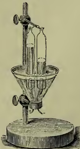
The ions, as they appear at the electrodes, may not be the real components of the electrolyte which are being urged in opposite directions through the liquid. In the case of fused silver chloride, the ions are no doubt these very components; but, in the case of dilute sulphuric acid, we have no right to regard hydrogen and oxygen as the real original products of electrolysis. Indeed, we know by experiment that the purer the water the greater its resistance; so that we have every reason to believe that absolutely pure water is a non-conductor and cannot be electrolysed. Probably the secondary actions which in the case of dilute acid transform the real original ions into oxygen and hydrogen may be somewhat similar to what is certainly part of the action when a solution of sulphate of soda is electrolysed. The components of the molecule are and —i.e. sodium and what is called sulphion. The sodium molecules drift with the current, the sulphion molecules against it. But the sodium, when it appears at the negative electrode, at once acts chemically on the water, forming soda, , and liberating hydrogen, . Again at the positive electrode, the sulphion not being able to exist in the free state, breaks up into and ; and then the sulphuric acid is dissolved up in the water, and oxygen is given off. Thus, again, the constituents of water, , appear as the ions, exactly as in the case of the dilute acid. Here, however, the molecule of the electrolyte is not really , but has so much water united with it. Thus there may be a direct decomposition of water, as well as of the sulphate of soda. Whatever the real process of electrolysis, it is certain that in many cases secondary chemical actions quite mask it. These secondary actions do not, however, affect the accuracy of the law of electrolysis. Whatever be the apparent products of decomposition, these, if they can be caught and measured, will appear in quantities proportional to their chemical equivalents. It is further evident that if one electro-chemical equivalent of an electrolyte is decomposed, it must be decomposed into components chemically equivalent to one another and to it. Hence it is enough to measure carefully the electro-chemical equivalent of one of the ions or products of decomposition. By means of a table of chemical equivalents we shall then be able to calculate the electro-chemical equivalents of given electrolytes. So many are the causes, both physical and chemical, which tend to disturb the perfect accumulation of the ions on or over the electrodes, that the accurate experimental determination of the electro-chemical equivalent is a matter of great difficulty. Large copper electrodes in copper sulphate yield fairly good results; but the only completely satisfactory combination is a particular solution of nitrate of silver with pure silver electrodes. The electrolysis of this electrolyte by means of a current, whose strength should be adjusted to the size of the electrodes, so as to give a particular amount of current per unit area, is accompanied by an accurate transference of so much silver from one electrode to the other. In other words, the one electrode loses as much as the other gains, a degree of perfection which is hardly ever attained in other cases. Recent independent determinations by Kohlrausch and Rayleigh agree to the fourth significant figure; so that we may safely say that the unit of current known as the ampère will reduce out of a solution of nitrate of silver 1.118 milligrammes of silver per second. This therefore is the electro-chemical equivalent of silver. Now in chemical combinations 216 grammes of silver correspond to 18 grammes of water and to 65 grammes of zinc. Hence a simple calculation gives .0932 milligrammes as the electro-chemical equivalent of water, and .336 milligrammes as the electro-chemical equivalent of zinc. The unit of current which has just been mentioned, the ampère namely, is one-tenth of the electro-magnetic unit of current, which may be defined in several ways (see MAGNETISM). For our present purpose, however, it will be sufficient to indicate experimentally what magnitude of current the ampère is. If an ampère is passing along a conductor of 1 ohm resistance—say, a column of mercury 106.3 centimetres long and 1 square millimetre cross-section—the electromotive force along the conductor—i.e. the difference of potential of its ends—will be the quantity known as 1 volt; and the volt is such that the electromotive force of a Daniell cell is about 1.08 volts. In connection with electric lighting, these units—the volt, the ampère, and the ohm—are in universal use.
Intimately connected with electrolysis is the theory of action of the ordinary galvanic or voltaic cell. For, whenever such cells are being used for the production of electric currents, there is going on within them chemical actions essentially electrolytic. Take, for example, the Daniell cell with its copper and zinc plates dipping respectively in solutions of copper and zinc sulphates. When the cell is closed, the current flows externally from the copper to the zinc, and internally from the zinc through the zinc and copper sulphates to the copper. The electrolysis of these electrolytes is a necessity, with the result that the zinc is gradually dissolved away, and copper deposited on the copper electrode. The net chemical result is the removal of copper from the sulphate and the substitution of an equivalent of zinc. But this chemical reaction is accompanied by the evolution of heat—i.e. the liberation of so much energy available for transformations. It is this energy which is the source of the electric energy when the replacement of copper by zinc in the sulphate is effected in the particular arrangement known as the Daniell cell. Now, according to Thomson's determinations of heats of combination, the consumption of 1 gramme of zinc in a Daniell cell means the evolution of 8053 gramme-degrees, that is, an amount of heat that would raise 8053 grammes of water . in temperature. Hence the consumption of an electro-chemical equivalent of zinc—i.e. .336 milligrammes—means the evolution of 2.706 gramme-degrees of heat. This then is the energy which is associated with the production of one unit of electricity. To reduce it to dynamic units we must multiply by the factor , which is the number of units of energy equivalent to the heat required to raise the temperature of 1 gramme of water . Thus we find as the energy which a Daniell cell liberates per second when it produces a current of 1 ampère. If is the electromotive force associated with this unit current, then measures the work done per second by the current; and assuming that this is the energy liberated in the cell, we find electro-magnetic (C. G. S.) units of electromotive force—i.e. 1.14 volts, according to the definition of a volt. This is slightly higher than the real value of the electromotive force of a Daniell cell, but it is close enough to warrant the conclusion, first enunciated by Sir William Thomson (1851), that the electromotive force of any electro-chemical apparatus is, in absolute measure, equal to the dynamical equivalent of the chemical action that takes place during the passage of unit current for unit time. There are many cases of galvanic combinations for which this principle fails to a degree which cannot be even approximately referred to errors of experiment. Some other principles, either chemical or physical, must be involved. There is no question, however, as to the general application of the law enunciated by Thomson.
We are now able to see why it is that one Daniell cell cannot effect an electrolysis in which the constituents of water appear as the ions. It is simply because the heat developed in the formation of an equivalent of water by direct union of its constituents is about half as great again as the heat evolved in the combustion of an equivalent of zinc in a Daniell cell. Hence to decompose an electro-chemical equivalent of water requires more energy than is supplied by the combustion of an electro-chemical equivalent of zinc in the cell.
The general principle here indicated may be stated thus: A current flowing through a given electrolyte decomposes electro-chemical equivalents in unit time. But this requires a definite amount of work done, which we may write , where measures the work which must be done to decompose one electro-chemical equivalent. Hence the energy of the current must be at least , or in other words, measures in absolute measure the smallest electromotive force with which distinct electrolysis can be effected.
All the phenomena which accompany simple electrolysis are encountered in the action of galvanic cells. The poles, like the electrodes, become, or tend to become, polarised. This is especially the case in single fluid cells, in which the apparent electromotive force very markedly diminishes during the first few moments of action, due to the reversed electromotive force of polarisation produced by the accumulation of the ions on the poles. In the so-called constant elements, such as the Daniell, the Bunsen, or the Grove, all of which are double-fluid cells, the ion is either of the same nature as the pole at which it appears, or is dissolved in the fluid so as not to accumulate. By such means the electromotive force is kept fairly constant so long as the strengths or characters of the solutions do not greatly alter. The chief conditions to be fulfilled by cells which are to yield strong steady currents are (1) small polarisation, (2) a plentiful supply of electrolyte, (3) a small resistance. This last condition is obtained by using large surfaces for the electrodes, which are opposed to each other as closely as the arrangements of the cell will permit.
The difficulties of measuring the true resistance of electrolytes, and therefore of galvanic cells, have already been touched upon. We must here confine ourselves to the chief results which experiment has established. As compared with metallic conductors, the specific resistance of electrolytes is very great. Then, again, rise of temperature diminishes the resistance of electrolytes, whereas, except for selenium, phosphorus, and carbon, it increases the resistance of simple conductors. Finally, in the case of solutions in water of such compounds as sulphuric acid, nitric acid, sulphates, chlorides, nitrates, and so on, there is in general a definite solution which conducts better than any other solution of the same substance—i.e. a definite percentage composition which is associated with a minimum specific resistance. In all cases a condition of infinite resistance is approximated to as the solution is taken weaker and weaker; and in some instances (sulphuric acid, for example) the same condition of infinite resistance is hinted at for infinitely strong solutions—i.e. for the pure non-hydrated substance. Kohlrausch, who has probably worked most extensively at this subject, speculates upon the necessity of solution or of mixture of stable chemical compounds before conduction can take place. In other words, such compounds, if absolutely pure, would be non-conductors.
We cannot hope to understand the true nature of resistance till we know what an electric current really is. The fact that electrolytes obey Ohm's Law as accurately as simple conductors suggests that the process of conduction is essentially the same in both, notwithstanding the many differences that exist in the accompanying phenomena. The view that an electric current is intermittent—i.e. is a succession of distinct discharges at extremely short intervals of time, is one which seems to be involved in all the best theories of electrolysis that have been elaborated. Maxwell has shown that a rapid intermittent charging and discharging can give rise to all the effects of a true resistance. Suppose we have a condenser of capacity , whose plates are, by means of a tuning-fork interrupter, alternately brought into contact with the poles of a battery and with each other, so that the condenser is charged and discharged times a second. If is the electromotive force of the battery, is the electricity which passes at each discharge. Hence in one second units of electricity pass; and this is the current . Thus
so that measures the conductivity. The greater is, the greater the conductivity, the less the resistance. Hence, if the electric current is of the nature of intermolecular discharge, we see that greater closeness of the molecules, being in all probability associated with more rapid charging and discharging, will give rise to less resistance. This would so far explain the much greater resistance of electrolytes as compared with metallic conductors. For a very complete statement of this view, consult Professor J. J. Thomson's Applications of Dynamics to Physics and Chemistry (1888).
The hypothesis just given of the intermittent character of electric conduction obviously suggests that the mode by which electric transference takes place in simple conductors, electrolytes, and dielectrics is fundamentally the same. In many dielectrics the phenomenon of 'leakage'—the name given to the gradual loss in charge of a conductor in contact with the dielectric—presents characteristics very similar to true ohmic conduction. Then dry glass, although a very good insulator at ordinary temperatures, becomes distinctly conducting at temperatures above .—a fact first noticed by Cavendish. Later experiments indicate that the conduction of hot glass is electrolytic, the electrodes becoming polarised. In the case of gases, electrical discharge seems always to be of an intermittent character. A certain electromotive force, depending on the shape and size of the electrodes, on their distance apart, and on the density, temperature, and nature of the gas, is necessary before discharge takes place. For smaller electromotive forces, the gas, if free from convection currents, seems to insulate perfectly. The insulating power of the gas under given conditions is measured by its dielectric strength, which varies as the square of the electric force. The dielectric strength increases markedly for very small distances between the electrodes, a very remarkable fact which may possibly be due to a greater density of gas close to the surfaces of the electrodes. For smaller and smaller distances such condensed layers would of course play a more pronounced rôle. This explanation agrees with the fact that the dielectric strength of gases diminishes as the density is diminished. This, however, does not go on indefinitely, but it reaches a minimum for a certain low density, which has a different value for each gas, and which is also a function of the diameter of the tube in which the rarefied gas is contained. A pressure of 2 or 3 millimetres of mercury gives the density for which the dielectric strength of air reaches its minimum. Further rarefaction beyond the point of minimum dielectric strength is accompanied by a rapid increase of insulating power, until at length it is impossible to make a discharge pass through the extremely attenuated gas. It thus appears that electricity cannot pass from electrode to electrode in a perfect vacuum—i.e. a region void of ordinary matter. Whether this is due to an infinite passage resistance between the electrodes and the so-called vacuum, or to the absolute non-conducting power of the vacuum, is a point not yet settled. Electric discharge through rarefied gases is accompanied by very beautiful luminous effects, which are often enhanced by the phosphorescence of the glass forming the vacuum tubes. These tubes are usually called Geissler tubes, after the first great maker of them (the glass-blower and mechanician, Heinrich Geissler, 1814-79). See VACUUM-TUBES, RÖNTGEN.
The polarisation of the electrodes during electrolysis has within the last ten years acquired a great practical importance in connection with the construction of secondary batteries or accumulators. An accumulator is simply a polarised electrolytic cell capable of supplying a steady current for a lengthened time. Theoretically of course, all polarised electrolytic cells are accumulators; but usually the currents they supply are short-lived and feeble. It was not till 1860 that Planté constructed an accumulator which could supply a really efficient current. The Planté secondary cell is formed by the electrolysis of dilute acid with lead electrodes. With sufficiently strong currents, the result of the electrolysis is that the positive electrode becomes covered with peroxide of lead (), while lead accumulates in a spongy form on the negative electrode. When the polarisation has been carried on to a sufficient extent, the cell is said to be charged, and it will be found to have all the properties of a true galvanic cell of low resistance and fairly high electromotive force (about 2 volts). On being closed, it will supply a current sufficient to keep a thin wire glowing for several hours. At the same time, the peroxide of lead will become reduced to a lower oxide, and the spongy lead will be oxidised, while the sulphuric acid present gives rise to other reactions. During the greater part of the discharge of the cell, the electromotive force remains very constant, and only begins to diminish as the depolarisation approaches completion. When the charged cell has thus, through use, lost nearly all its accumulated electrical energy, it is put into circuit with a primary source of current energy and re-charged. The modifications of construction introduced by Faure in 1881 gave a great impulse to the development of accumulators as a practical source of electrical energy. Instead of using merely lead sheets as electrodes, Faure covers them first with a layer of minium or red lead. With these as electrodes the electrolysis of dilute sulphuric acid is effected, the result being, as before, the formation of peroxide of lead at the positive electrode and spongy lead at the negative electrode. What chemical reactions take place as the accumulator discharges itself are not fully understood. The final result, however, seems to be the formation of sulphate of lead on both electrodes. Re-charging from a prime source restores the peroxide of lead and the spongy lead as in the first charging. As part of the recent development in electric lighting, the efficiency of accumulators has been greatly increased; and they are now largely used as the direct source of power. They must, of course, be charged and re-charged at intervals depending upon the particular rate at which they are made to give off their stored-up energy. A battery of Bunsen or other cells may be used for charging purposes; but if the wasteful voltaic cell had been our only prime source of electric energy, the secondary cell could never have assumed the practical importance it has. It is because we can generate electric energy dynamically and economically (see MAGNETISM) that we find a use for the accumulator, which is simply an arrangement for the storage of so much electrical energy in a form convenient for future purposes.
Of all the thermal effects produced by currents, the Joule Effect is the most conspicuous and by far the most important. But there are other thermal effects which are associated with the transference of electricity, and which are readily distinguished from the Joule effect by what is known as their reversible character. Thus the Joule effect always means a rise of temperature in the conductor whatever the direction of the current through it; whereas these so-called reversible effects mean a rise of temperature when the current passes in the one direction, and a fall when it passes in the other. If at any part of a circuit, in which a current is flowing, a fall of temperature is observed, we are probably safe in regarding this cooling effect as one of these reversible effects. We may test this directly by reversing the current; but occasionally the conditions of the experiment may prevent the application of this test. Thus, in some cases, a galvanic cell, in circuit with a large external resistance, is found to cool. Since the current due to a given galvanic combination must always flow in the same direction through the cell, it is impossible of course to apply the test of reversal. Other galvanic cells, again, when similarly joined up with a high external resistance, are found to rise in temperature under conditions in which the true Joule effect is inappreciable. Such thermal effects seem to be true reversible effects; and upon them Von Helmholtz bases his explanation of the apparent failure, in many instances, of Thomson's dynamical theory of the electromotive force of a battery (see above). In most cases, the electromotive force is smaller than what the chemical reactions imply; but in some it is greater. In the former there is intrinsic heating in the cell; in the latter there is cooling—exactly the relations which the principles of energy require. For, as in the latter case, if the electrical energy generated is greater than the chemical energy supplied, it must borrow heat from the surrounding substances to make up its surplus energy. The further fact that those cells, which either heat or cool of themselves, have electromotive forces which vary with temperature, points to these being truly reversible thermal effects. An electromotive force which grows with temperature is associated with a cooling effect in the cell as the current is flowing, while an electromotive force which diminishes with rise of temperature is associated with a heating effect. This must be so; for in all cases of transformations of energy, the final effects react so as to resist the changes that lead to them. In the present case, if a heating effect co-existed with an electromotive force which increased with temperature, this heating effect would raise the temperature still further, increase the electromotive force still more, and cause a stronger current to flow, which in its turn would cause a further rise of temperature, and so on indefinitely—an obvious contradiction of all experience. We shall find some simple applications of the same dynamic principle of reaction in the other reversible thermal effects of electric currents. These are intimately connected with the whole subject of thermo-electricity, which we shall now discuss.
Thermo-electricity dates from 1821, when Seebeck discovered that a current was generated in a circuit composed of copper and antimony, when the junctions were at different temperatures. With a sufficiently delicate galvanometer, the same phenomenon may be shown not only with any two different metals, but also with the same metal in two different conditions. Thus, a stretched, twisted, or (if possible) magnetised wire will give thermo-electric currents with a piece of the same wire which has not been so treated. Slight impurities cause distinct changes in thermo-electric properties; indeed, thermo-electric currents may often be obtained in a circuit of two wires, which no other physical test can differentiate. The fundamental fact of thermo-electricity is that, in a circuit built of two or more different conductors, a current is in general generated when one junction at least differs in temperature from the others. For the sake of definiteness, consider a circuit of
Fig. 28.
the two metals iron and copper, with their junctions at A and B, and with a delicate galvanometer included for the measurement of current. If A and B are at different temperatures, a current will in general be set up in the circuit; and for moderate temperatures up to . or so, this current will flow from copper to iron through the warmer junction, and from iron to copper through the colder junction. Now this current must derive its energy, , from some source; and the only source that exists is the heat which is available in virtue of the unequal distribution of temperature. In virtue of thermal conduction and radiation, the tendency is towards an equalisation of temperature, the warmer junction losing heat, and perhaps the colder junction gaining heat. But if this heat is also being partly drawn upon to sustain an electric current, the equalisation of temperature will be hastened because of this transformation into electric energy. Hence, we should expect the thermo-electric current to be associated with, at any rate, a cooling effect at the warmer junction. That such an effect really does exist was established experimentally in 1834 by Peltier—hence the name Peltier Effect. He showed that heat is absorbed or evolved at the junction of two different metals, across which any current is made to pass; and that if the direction of this current is the same as that of the thermo-electric current that would be produced by heating the junction, the effect is absorption of heat—i.e. cooling; and vice versa. Thus, in a copper-iron circuit at moderate temperatures, the thermo-electric current is associated with a cooling effect at the warmer junction, and a heating effect at the colder junction. Icilius proved by experiment (1853) that the Peltier effect is proportional to the strength of the current. It is also known to vary with the temperature, sometimes increasing with rise of temperature, sometimes diminishing, according to the particular kinds of metals used.
The Peltier effect is defined as the heat absorbed by the passage of unit of electricity in the proper direction across the junction; or otherwise, the heat absorbed per second by the passage of unit current. Let be the Peltier effect at the warmer junction of a thermo-electric circuit, and its value at the other junction. Assuming that the Joule and Peltier effects are the only thermal accompaniments of a thermo-electric current , we find for the whole amount of heat absorbed the quantity , and for the whole amount of heat evolved , where is the resistance of the circuit, and where the heats are estimated in dynamic units. If we suppose these to be the only transformations of energy involved, we have at once
In the latter equation, the difference of the Peltier effects appears as the electromotive force associated with the current . From this point of view the Peltier effect is to be regarded as an abrupt change of potential at the junction of the two metals. It must not be confused, however, with the electromotive force of contact discovered by Volta, compared with which it is extremely small, and frequently of opposite sign.
Thus we may suppose thermo-electric currents to be explained in terms of the Peltier effects, regarded as electromotive forces at the junctions. But the striking phenomenon of thermo-electric inversion, discovered by Cumming in 1823, necessitates the supposition of other than Peltier effects for a satisfactory explanation of thermo-electric currents. Take, for example, the copper-iron circuit, keep the one junction B at a steady temperature of, say, , and raise the temperature of the other junction A steadily and indefinitely from . to about a dull red heat. As the temperature of A rises, the current setting from copper to iron through A will increase to a maximum, then decrease to zero, and finally become reversed. The temperature at which this maximum current is obtained is a definite temperature for a given pair of metals, being quite independent of the temperature of the other junction. It is called the Neutral Point. If the temperature of the one junction is as much above the neutral temperature as the temperature of the other junction is below it, there is no current; and the mean of these two temperatures is the neutral temperature. For copper-iron the neutral point is about .; for zinc-iron, about .; for cadmium-iron, about .; and so on. In the majority of cases, the neutral point, occurring either above or below ordinary ranges of temperature, cannot be easily observed directly; but its position is usually indicated by the manner in which the electromotive force is found to vary with temperature. Now suppose that the one junction A in the copper-iron circuit is kept at the neutral temperature ( say); then whatever be the temperature of the other junction, whether it is higher or lower than ,
Fig. 29.
the direction of the current will always be the same—viz. from copper to iron through the junction A. Consider the two cases: (1) B at temperature ; (2) B at temperature . In the first case, if the only reversible thermal effects existing are the Peltier effects at the junctions, then there must be absorption of heat at A (copper to iron), and (if anything) evolution of heat at B (iron to copper). But in the second case, the same assumption requires that there must be absorption of heat at B (iron to copper), and (if anything) evolution of heat at A (copper to iron). Now these two statements are incompatible unless there be neither absorption nor evolution of heat at A—i.e. unless the Peltier effect vanish at the neutral point. But this being so, it is at once evident that in the first case there is no absorption of heat at all. Heat is evolved at B, and heat is evolved because of the Joule effect; but there is no evidence of any absorption of heat to account for the energy of the current. Hence the original assumption must be wrong—i.e. there must be other reversible effects in the circuit besides the Peltier effects at the junctions. There must be a cooling effect either in the copper wire, or in the iron wire, or possibly in both. This theoretical conclusion was first obtained by Sir William Thomson (1851), who proceeded at once to test it by an appeal to experiment. It was found that both of these predicted effects take place. A current passing from cold to hot in copper is associated with an absorption of heat; while heat is evolved if the current passes from hot to cold. On the other hand, for iron, things are just reversed; cooling is associated with the current that flows from hot to cold, and heating with the current that flows from cold to hot. This reversible thermal effect which accompanies the passage of a current in an unequally heated conductor is called the Thomson Effect. It is said to be positive in copper; and is therefore negative in iron. Cadmium, zinc, silver, gold, nickel between the temperatures of 250° C. and 310° C., and iron above a dull red heat, have, according to Professor Tait's experiments, their Thomson effects also positive. Platinum, palladium, potassium, sodium, cobalt, nickel below 200° and above 320°, and probably iron again above a bright red heat, are examples of metals having negative Thomson effects. The Thomson effect has been measured directly in a very few cases; but it may be calculated from thermo-electric constants, if Tait's hypothesis be true (and recent direct experiments go far to verify it) that the Thomson effect is for most metals directly as the mean absolute temperature. The extraordinary change of sign in the Thomson effect, which Tait discovered to exist both in nickel and iron at certain temperatures, is an extremely interesting phenomenon, and seems to be connected with other properties peculiar to these magnetic metals—such as their loss of magnetic susceptibility and the manner in which their electrical resistances change with temperature.
In comparison with the electromotive forces of voltaic cells, the electromotive forces that can be obtained with thermo-electric circuits are usually very small. Thus copper-iron with one junction at 275° C., and the other at 0° C., has an electromotive force of only .0022 volts. The electromotive force of an iron-nickel pair with junctions at temperatures 0° C. and 200° C. is .008 volts; and the electromotive force of a bismuth-antimony pair with a difference of temperature of 50° C. is about .005 volts. Bismuth and antimony are, because of their high mutual thermo-electromotive force, ordinarily employed in the construction of the thermopile, a valuable instrument for indicating and measuring small variations of temperature.
Fig. 30.
It consists of alternate strips of bismuth and antimony forming a continuous zigzag chain, as indicated in fig. 30. They are arranged in compact form so that the successive junctions alternate, now on this side, now on that side, forming two plane faces looking opposite ways. If a source of heat is brought opposite to the one face, the junctions ending there are heated by radiation, while the alternating junctions on the other face remain at the temperature of the air. Each pair of junctions gives rise to a thermo-electromotive force , and therefore the pairs to . If is the resistance of each pair of strips, and the resist- ance of the galvanometer and connecting wires, the current is given by the equation
Thus is always greater than the greater is; and if, as is usually the case, the resistance of the thermopile () is small compared with the resistance of the galvanometer, the current due to the pairs is very nearly times the current that one pair would give. Thus a thermopile of thirty-six pairs of junctions will give an electromotive of nearly one-tenth of a volt for a difference of temperature between the faces of 25° C.
The Peltier effect between bismuth and antimony at the ordinary temperature of the air is about per ampère per second, estimated in dynamic units—i.e. about .0075 in gramme-degree units of heat. Hence in one minute, a current of one ampère passing from antimony to bismuth will evolve a quantity of heat sufficient to raise a gramme of water nearly half a degree centigrade in temperature. For other ordinary pairs of metals, the Peltier effect is considerably smaller than that just given. Thus for iron-copper at the ordinary temperature of the air, the Peltier effect is about one-seventh of its value for bismuth and antimony.
The Thomson effects are extremely difficult to measure directly. We may, however, get an idea of their magnitudes by calculating them according to Tait's theory from the thermo-electric constants. Suppose, for example, that a current of ten ampères is flowing along an iron or copper wire, whose ends are at 0° C. and 100° C. Then the amounts of heat in gramme-degrees evolved or absorbed per minute are, in iron .224, in copper .044. These numbers are calculated on the assumption that the Thomson effect in lead is nil, an assumption based on the direct experiments of Le Roux.
In recent years an extensive literature bearing on electricity has sprung up. Of elementary text-books fitted for the use of students, we may mention Fleming Jenkins' Electricity and Magnetism (Longmans, Green, and Co.), specially good in the practical experimental part of the subject; Ferguson's Electricity (W. & R. Chambers, new edition by Professor Blyth, 1882), perhaps the most consistent of elementary treatises in its adherence to the Faraday conception of electric and magnetic action; Cumming's Theory of Electricity (Macmillan & Co., 1876); and Maxwell's Elementary Treatise on Electricity (Clarendon Press, 1881), unfortunately only a fragment. Of complete treatises, Maxwell's Electricity and Magnetism (Clarendon Press, 1873; 2d ed. 1881) is the great modern classic on the subject. Professor Chrystal's article 'Electricity' in the Encyclopaedia Britannica is an admirable and compact exposition of the science up to the date of publication. Wiedemann's Die Lehre von der Electricität (4 vols. 1882-85) is invaluable as a book of reference. Mascart and Joubert's L'Electricité et le Magnetisme (2 vols. 1882-86) has been translated into English by Dr Atkinson, and Foster's Elementary Treatise (1896) is based on it. See also J. J. Thomson's Elements of the Mathematical Theory of Electricity and Magnetism (1895). The development of the modern theory of electricity is to be traced chiefly through the original writings of Poisson, Ampère, Gauss, Joule, Green, Faraday, Thomson, Maxwell, and Helmholtz; and of these the Experimental Researches of Faraday (3 vols. 1839-44-55) will always hold an altogether unique position.
In the preceding article the aim has been to present the science as a unity, especially in relation to the modern doctrine of Energy; only in this way can justice be done to such important subdivisions as Electrolysis and Thermo-electricity. It has been found convenient, however, to omit the whole of Electro-kinetics and Electro-magnetism, as these are in reality best discussed under MAGNETISM. In the presentation of the facts and theories of what is commonly called Frictional Electricity or Electrostatics, the conceptions of Faraday, as interpreted and extended by Thomson and Maxwell, have been closely followed. In no case has the ordinary two-fluid theory been made explicit use of; although it is quite impossible to escape altogether from its implication in the nomenclature which has survived the theory that gave it birth. The history of the science will be found treated incidentally, as the successive points are taken up in order. For convenience of reference, we give an epitome of the arrangement of the article. Electrostatics takes up nearly the half of the article, and is followed by Electro-kinematics, Electrolysis, and Thermo-electricity in order, thus :
Electrification, page 255.
Electroscope, electrometer, page 256.
Fundamental experiments, page 256.
Potential; equipotential surfaces, lines of force, page 253.
Capacity; concentric spheres, parallel planes, page 260.
Absolute measurement of electric quantities, page 262.
Specific inductive capacity, page 263.
Instruments for generating electricity, page 263.
Loss of energy at discharge, page 264.
Transference of charge, current, page 264.
Galvanometer, page 265.
Electromotive force, page 266.
Resistance, Ohm's Law, page 267.
Joule's Law, page 269.
Electrolysis, page 270.
Energy relations of voltaic cells, page 272.
Conduction and discharge compared, page 274.
Secondary batteries, page 275.
Reversible thermal effects of currents, page 275.
Thermo-electricity, page 275.