Horology (Lat. horologium, Gr. hōrologion, 'a sun-dial,' 'a water-clock'; Gr. hōra, 'a season,' 'an hour,' and -logion, from legein, 'to tell,' compare Old Eng. horologe, Fr. horloge, 'a clock'), the science which treats of the construction of machines for telling the time. Although it is easy to look back to a period when time, according to the modern conception of it, as measured by hours and minutes and seconds, was unknown, yet we find progress early made in the measurement of larger periods of time, by observations of the heavenly bodies. Thus, time was early divided into years according to the apparent motion of the sun among the constellations; into months by the revolution of the moon round the earth; and into days by the alternate light and darkness caused by the rising and setting of the sun. It was long, however, before any accurate measure was found for a division of the day itself. The earliest measure employed for this purpose that we can trace is the shadow of an upright object, which gave a rough measure of time by the variations in its length and position. This suggested the invention of sun-dials (see DIAL). Another means early adopted for the measurement of short periods of time was by noting the quantity of water discharged through a small orifice in the containing vessel. Instruments for the measurement of time on this principle were called Clepsydræ (q.v.). The running of fine sand from one vessel into another was found to afford a still more certain measure, and hence the invention of the Hour-glass (q.v.). King Alfred is said to have observed the lapse of time by noting the gradual shortening of a lighted candle.
It is not very easy to trace to its source the history of the invention to which the modern clock owes its parentage, as there are many vague allusions to horologies from a very early period; but whether these were some form of water-clock or wheel-and-weight clock is uncertain. But there seems little reason to doubt that Gerbert, a distinguished Benedictine monk (afterwards Pope Sylvester II.), made a clock for Magdeburg in 996, which had a weight for motive power; and that weight-clocks began to be used in the monasteries of Europe in the 11th century; though it is probable that these only struck a bell at certain intervals as a call to prayers, and had no dial to show the time. St Paul's Cathedral had a 'clock-keeper' in 1286, and presumably a clock; and Westminster possessed one about 1290, and Canterbury Cathedral about 1292. An entry in the patent rolls of the eleventh year of Edward II. (1318) proves that Exeter Cathedral had a clock in that year, and St Albans, Glastonbury, Padua, Strasburg, and many other places possessed them in the first half of the 14th century. The St Albans clock was a famous astronomical one made by Richard de Wallingford, who was son of a blacksmith of St Albans, and afterwards became abbot there (1326-34). The clock made for Glastonbury Abbey by Peter Lightfoot, a resident monk (about 1325), was removed in the reign of Henry VIII. to Wells Cathedral, and is now preserved in South Kensington Museum; as is also an old clock from Dover Castle, bearing the date 1348, and the initials R.L. in monogram. The original great clock at Strasburg Cathedral was made in the years 1352-70 (remodelled and reconstructed in 1571-74). A clock much superior to anything preceding it was that made by Henry de Vick (or Wick) for the tower of
Charles V.'s palace at Paris in 1370-79. It was said to be on the bell of this clock that the signal was given for the massacre of St Bartholomew, 1572. By successive improvements clocks have gradually developed into the beautiful pieces of mechanism of the present day. Many curious and interesting specimens, such as that of Strasburg (q.v.) (1594), Lyons Cathedral (1598), St Dunstan's, London (1671; removed to a house in Regent's Park, 1831), and many others, have an historical interest. Many curiosities of mechanism are still constricted in the name of clocks, but generally eccentricity is their only feature. Those interested in the subject will find much information in Wood's Curiosities of Clocks and Watches (1866).
The date when portable clocks were first made cannot be determined. They are mentioned in the beginning of the 14th century. The motive power must have been a mainspring instead of a weight. The Society of Antiquaries of England possesses one with the inscription in Bohemian that it was made at Prague by Jacob Zech in 1525. It has a spring as motive power with fusee, and is one of the oldest portable clocks in a perfect state in England.
Illuminated clock dials, to shine at night, were introduced in the first quarter of the 19th century.
Clocks are of many and various kinds—striking and non-striking—turret-clocks big enough to carry hands 6 to 10 feet long and to ring a bell to be heard at 20 miles' distance, the good old-fashioned eight-day clock with its long case, the ornamental drawing-room spring clocks, Dutch clocks, American clocks, and an infinity of others. Technically, those which strike are called clocks, and those which do not strike, timepieces, irrespective of size. But, however much they may vary in size and appearance, they are all founded on the same principle, and it will answer our present purpose to illustrate that principle in its more ordinary form of the household clock.
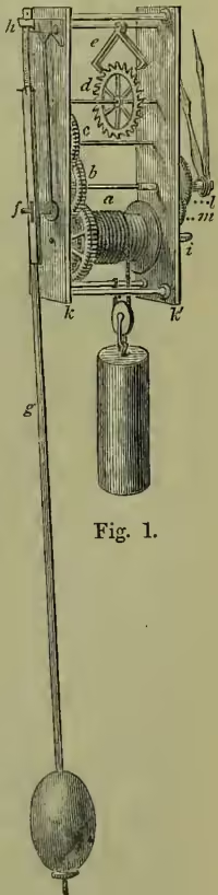
Fig. 1 represents a diagram of a non-striking timepiece. A weight, by turning a barrel, a, on which its cord is wound, sets in motion a train of wheels, b, c, terminating in the crown-wheel or escapement-wheel, d. These wheels are set between two plates which are fixed together by four pillars, one at each corner; the pillars are riveted into the back plate, k, and fastened with movable pins into the front plate, k'. The dial, removed in the fig., is also pinned on to the front plate by four short pillars or feet. The teeth in the pinions and wheels are so arranged in number that, while the crown-wheel revolves in 60 seconds, the centre wheel, b, takes an hour to do so. To regulate the speed at which the clock shall move, an arrangement called an escapement, e (to be afterwards more fully described), communicates by means of its crutch (at f) with the pendulum, g, which is suspended by a spring from the cock at h. The arbor of the barrel extends in a square form to the dial at i, where it is wound up; a ratchet preventing its unwinding without turning the wheel with it. The hands have a separate train of wheels, called the dial or motion train, between the front plate and the dial. The arbor of the centre wheel, b, is produced to the dial, and on it is put the minute-wheel, revolving once an hour, with a long socket on which the minute-hand is fixed. Over this is placed a larger wheel, the hour-wheel, l, revolving in twelve hours, which is set in motion by the pinion of a duplicate minute-wheel, m (and also seen at h, fig. 6). The attachment of the minute-wheel to the centre-wheel arbor is, by means of a spring, enough to ensure the hands being carried round with the clock, but not enough to prevent the hands being turned, when necessary, by hand, without disturbing the interior works.
Striking-clocks have an additional train of wheels with separate weight (or spring) for the striking; it will be described further on.
Spring-clocks—i.e. clocks having a coiled spring as a motive power instead of a falling weight—have an arrangement of barrel and fusee chain similar to that of the watch, to be afterwards described. The spring is used when it is wished to save space, as the necessary fall of a weight requires a case deep enough to hold it, something about 4 feet for an eight-day clock. Their size also necessitates a short pendulum, which, of course, does not indicate seconds.
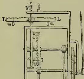
Previous to the invention of the pendulum, the regulating apparatus was generally as shown in fig. 2, which represents part of De Vick's clock already mentioned. The teeth of the escape-wheel, I, acting on the two pallets, h, i, attached to the upright spindle or arbor, KM, to which is fixed the balance, LL, gave to the latter an alternate or vibrating motion, which was regulated by two small weights, m, m. The further these weights were moved from the centre, the more they retarded the movement; and, by means of numerous notches, their position could be shifted till the proper speed was secured.
The great epoch in the history of horology was the introduction of the Pendulum (q.v.) as a regulating power. This has generally been attributed to Huygens, a Dutch philosopher, who was undoubtedly the first to bring it into practical use (1657). The fact of the actual invention, however, is obscure, and Sir E. Beckett says: 'The first pendulum clock was made for St Paul's church, in Covent Garden, by Harris, a London clock-maker, in 1621, though the credit of the invention was claimed also by Huygens himself, and by Galileo's son, and Avicenna, and the celebrated Dr Hooke.' In adapting the pendulum to the clocks previously existing Huygens had only to add a new wheel and pinion to the movement, to enable him to place the crown-wheel and spindle in a horizontal instead of a perpendicular position, so that the balance, instead of being horizontal as in De Vick's clock, should be perpendicular and extended downwards, forming a pendulum at one end.
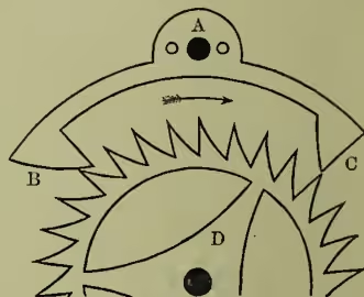
The principle of construction adopted by Huygens, from the peculiar action of the levers and spindle, required a light pendulum and great arcs of oscillation; and it was consequently said that 'Huygens's clock governed the pendulum, whereas the pendulum ought to govern the clock.' About ten years afterwards the celebrated Dr Hooke invented an escapement which enabled a less maintaining power to impel a heavier pendulum. The pendulum, too, making smaller arcs of vibration, was less resisted by the air, and therefore performed its motion with greater regularity. This device is called the anchor escapement. It was brought by Hooke before the notice of the Royal Society in 1666; and was practically introduced into the art of clock-making by Clement, a London clock-maker, in 1680. It is the escapement still most usually employed in ordinary English clocks. Fig. 3 represents the more modern form of the anchor or recoil escapement: A, its axis; BC, the pallets; and D, the escapement-wheel revolving in the direction of the arrow. The connection between the pendulum and escapement may be seen in fig. 1. When the pendulum swings to the right AC rises, and a tooth escapes from C, while another falls on the outside of B, and, owing to the form of the pallet B, the train goes back during the remainder of the swing. The same thing occurs on the pendulum's return; the arm AB rises, a tooth escapes from B, and another falls on the inside of C and backs the wheelwork as before. As each of the thirty teeth of the wheel thus acts twice on the pallets, at B and again at C, it follows that a hand fixed on its arbor will move forward th of a circle with each vibration of the pendulum and mark seconds on the dial. At each contact the onward pressure of the wheel gives an impulse to the pendulum, communicated through the crutch, sufficient to counteract the retarding effects of the resistance of the air and friction, which would otherwise bring it to a standstill. The length of a pendulum oscillating seconds is, for the latitude of London, about 39.14 inches.
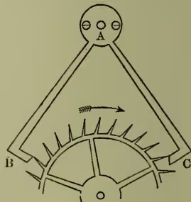
The defect of Hooke's escapement is the recoil, and various modifications have been devised to obviate this. The first and most successful was made by George Graham, an English watch-maker, in the beginning of the 18th century, and his improved form is called the dead-beat escapement (fig. 4). There the outer surface of B and inner surface of C are arcs of circles whose centre is A, and a little consideration will show that there can be no recoil. This escapement is adopted in time-keepers when great accuracy is required.
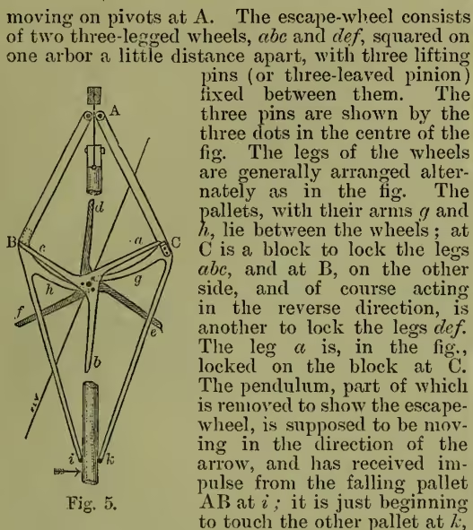
Many other escapements for clocks have been devised; but no one seems to have met with general favour except a certain form of remontoire or gravity escapement. The form of it shown in fig. 5 is called the double three-legged escapement, and was invented for the great clock at Westminster, in 1854, by E. B. Denison (afterwards Sir E. Beckett, Q.C.). In this clock the pendulum is 13 feet inch long, to vibrate in two seconds, and its bob weighs 6 cwt. The escapement consists of two gravity impulse pallets, AB and AC, which has been kept in position clear of the pendulum by one of the centre pins bearing on the arm g. The pendulum before turning again moves the pallet AC just enough to allow the leg a to escape from the locking-block at C; the wheel flies round, impelled by the clock-weight, till the leg f locks on the block at B; by the same movement the pin which is seen near the end of the arm h pushes the pallet AB away from the pendulum, which now gets impulse from the fall of the pallet AC. This goes on at each side alternately, the pallets being raised by the clock train, the pendulum only unlocking them. To make the motion go smoothly and prevent jar, a fly is attached to the arbor of the escape-wheel by a spring; it is seen in the figure. As the height to which the pallets are lifted is the same, however unequal the force communicated by the train may be, the arc of vibration of the pendulum remains constant, as the weight of the arm and the distance it falls are always the same.
The gradual perfection of the clock required also improvements in the regulating power which finally resulted in the compensation pendulum (see PENDULUM).
The improvements in the escapement and the pendulum bring the mechanical perfection of the clock, as a time-keeping instrument, to the point which it has attained at the present day. But the art of horology would be incomplete unless there were some standard, independent of individual mechanical contrivances, by which the errors of each may be corrected. This standard is supplied by observatories, and the methods by which time is determined belong to the details of practical astronomy. There are in most parts of the United Kingdom now sufficient opportunities of setting clocks by a communication more or less direct with these establishments. When these are not to be had the sun-dial may still be used with advantage as a means of approximation to the correct time. The time which a clock ought to mark is mean time, the definition of which will be found in the articles DAY and TIME. The mean time at any place depends on the longitude. Supposing a clock to be set to Greenwich mean time, a clock keeping mean time of any place will be 4 minutes faster for every degree of longitude east of Greenwich, and 4 minutes slower for every degree west. Since the introduction of railways, clocks are usually set within Great Britain to Greenwich mean time. In the United States, where the extent of country makes it unadvisable to use the mean time of one meridian, four standard meridians were adopted in 1883—viz. 75°, 90°, 105°, 120° west of Greenwich. Clocks showing ‘Eastern,’ ‘Central,’ ‘Mountain,’ and ‘Pacific’ time are therefore respectively five, six, seven, or eight hours slower than Greenwich mean time.
For the more ready transmission of correct time to the public there is at Greenwich Observatory, as well as some others, a ball which is dropped by means of electricity precisely at one o'clock. Several attempts have been made to keep the public clocks of a town in perfect agreement with the mean-time clock in the observatory. One means of effecting this was by an electric connection and a modification of Bain's electric pendulum (1840), by Mr R. L. Jones of Chester (1857), on the suggestion of Mr Hartnup, the astronomer of the Liverpool Observatory. For a description, see ELECTRIC CLOCK. A clock in the castle of Edinburgh, by whose mechanism a gun is fired precisely at one o'clock every day, is controlled by the mean-time clock in the observatory on the Calton Hill.
It is not known when the alarm or when the striking-mechanism of the clock was first applied. The first striking-clock probably announced the hour by a single blow, as they still do in churches to avoid noise. During the 17th century there existed a great taste for striking-clocks, and hence a great variety of them. Several of Tompion's (died 1713) clocks not only struck the quarters on eight bells, but also the hour after each quarter.
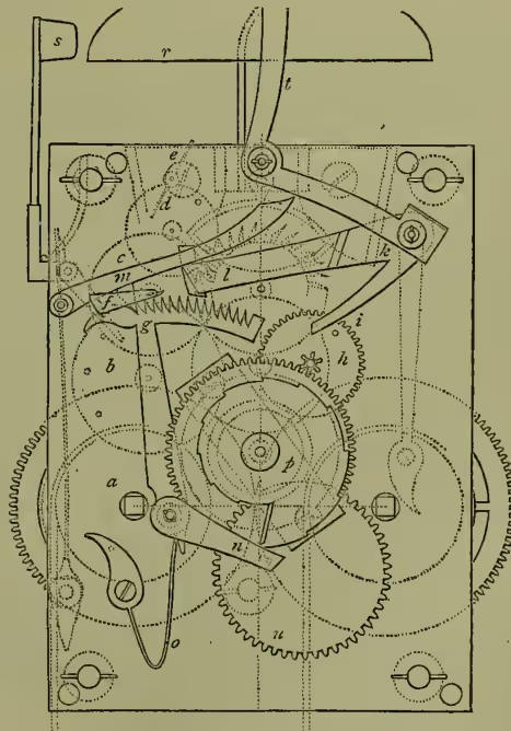
The striking part of a clock (see fig. 6, which shows an English striking-clock by Ellicott, taken from the engraving in Moinet's work) is a peculiar and intricate piece of mechanism. The motive power is a weight used in a similar manner to that in the time-keeping train shown in fig. 1. In fig. 6, a, b, c, d, e are the striking-train; e is a fly which acts as a drag to prevent the striking being too rapid. The striking-train is kept in a normal condition of rest by the tumbler or gathering pallet , fixed to the prolonged arbor of the wheel , being caught by the pin at the end of the rack . A few minutes before the hour, a pin on the wheel, , of the dial-train, raises the arm, , of the lifter , which in turn lifts the lever , which has by means of its hook been holding the rack, , fixed. The tail end, , of the rack is then forced by the spring, , against the 'snail' . The snail is attached to the hour-wheel of the dial-train (see fig. 1), and consequently revolves in twelve hours, and has a step for every hour. The rack, in falling on it, is freed to the extent of a tooth (i.e. a tooth gets past the hook at ) for every step of the snail. As shown in the fig., one tooth would be freed, and the result would be that the clock would strike one; when the last step of the snail is reached, twelve would be struck. The result of this movement is that the striking-train moves a little till a pin on the wheel catches on the end of the lifter , which is turned down through a hole in the plate for the purpose. The resulting sound is called 'warning.' Precisely at the hour the pin on the wheel slips past the end, , of the lifter, which falls, relieving the striking-train; the hours are struck on the bell , by the hammer , acted on by the pins on the wheel . As the tumbler attached to the wheel revolves once for every stroke of the bell, it gathers up a notch of the rack at each revolution, until it is stopped by a return to its original position of rest at the pin on the rack . The rack, lever, and lifting-piece are above the front plate, and are pivoted on studs fixed into it. A lever, , moved by a pointer on the dial, throws the striking work out of gear when the clock is required to be silent. In the fig. is an extra wheel for driving a hand to show the days of the month.
Clocks which chime the quarters and half-hours have generally a third train of wheels for the chiming.
In England clocks are principally made in London and Handsworth near Birmingham, though there are many small local makers. Many of the ornamental clocks and timepieces are manufactured in France.
Dutch or wooden clocks were first introduced about the middle of the 17th century. Though made on the same principle as ordinary clocks, their arrangements are much simplified, and their principal parts made of wood and wire, only the actual wheels being brass. They are very cheap, and consequently became very common in lower-class households and kitchens. They are made in the Black Forest in Germany, and, considering their mode of manufacture, are wonderfully accurate as timekeepers when properly taken care of.
They are now rapidly being superseded by American clocks, which, on account of their cheapness, neatness, and portability, have become very popular. Their manufacture is a great industry in the United States, at Waterbury in Connecticut, Brooklyn, New York, and many other places. The wheels and plates are stamped, and very little manual labour is spent on them, every part being interchangeable in similar-sized clocks. Their appearance is too familiar to require a detailed description. To many of these cheap clocks alarms are fitted, which can be set to sound at any hour. See ALARM.
Watches.—The modern perfect watch and chronometer may be said to be the result of a gradual development from the early clock rather than that of any particular invention. The first step was obviously to find some other form of power than the weight; and this was made in the end of the 15th century by the invention of the coiled spring as a motive power, but where, or by whom, is uncertain.
It seems to be taken for granted that Peter Hele, a mechanic of Nuremberg, as early as 1490 made small pocket clocks of steel which showed and struck the hours, and were driven by a coiled spring. These from their oval shape were called Nuremberg eggs. The next step was the invention of the fusee, an arrangement to overcome the weakening of the spring as it became uncoiled. This also is involved in obscurity, though it must have occurred early in the 16th century, as the clock mentioned as made by Jacob Zech in 1525 has that modification. At first a gut cord was used, the chain being a modern invention. The balance used was exactly like that of De Vick's clock (fig. 2), except that the weights on the arms of it were fixed instead of hanging. The next step of any consequence was the invention of the balance-spring by Dr Hooke in 1658-60, which was the foundation of all the varied improvements resulting in the almost perfect chronometer compensation-balance of the present day.
Although watches were introduced into England in Henry VIII.'s time, they did not come into general use till the reign of Elizabeth, and then their cost confined them to the wealthy. At first they were very large, on account of their striking part; and their cases, without glass, were pierced with elaborate open work to let out the sound of the bell. When the striking work was dispensed with, they of course became much smaller, and gradually drifted into being ornamental rather than useful. They were richly ornamented with pictures in enamel, set in the heads of walking-sticks, in bracelets, in finger-rings, and enriched with the most costly jewels. They were encased in crystal and in imitation skulls, and in fact became subject to all the vicissitudes of fashion, through which it would be needless for us to follow them. The curious will find much entertaining matter in Wood's work already referred to. Previous to the invention of the balance-spring, watches (as also clocks) had only one hand, which showed the hours; but after that event the greater power of regulating the motion led to the introduction of extra wheels to carry minute, and finally seconds, hands.
The watch is essentially a miniature edition of the ordinary spring-clock, except in two points—viz. that it has a balance-spring instead of a short pendulum, and that, as the escapement-wheel revolves in about six seconds, an extra wheel revolving in a minute is introduced to carry the seconds hand.
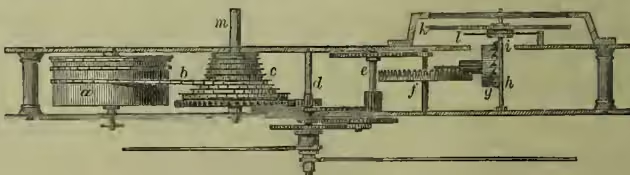
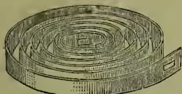
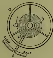
The train of an ordinary verge watch is shown in fig. 7: is the barrel enclosing the mainspring and turning, by means of the fusee chain , the fusee and great wheel , and, through the pinions and wheels , the escape-wheel . The hands or motion train are exactly as described for clocks, and are similarly carried by the elongated arbor of the centre-wheel . As will be seen in the fig., the fusee is of a peculiar shape. The reason is as follows: When the chain, which is fixed at the broadest part of the fusee, is fully wound up, it goes from the narrow part to the barrel where the other end is fixed, and of course the spring is also fully wound. At this point the spring is strongest; and, pulling upon the narrow end of the fusee, has the least leverage. As it gradually unwinds, and at the same time becomes weaker, the leverage, owing to the shape of the fusee, becomes in exactly the same ratio greater, and thus the power on the machinery is equalised till the whole chain is unwound. The spring is wound up by the squared arbor, m, of the fusee through an opening in the inside case; the arbor of the spring-barrel being of course fixed. An ingenious stop arrangement prevents the possibility of damage by over-winding. The mainspring is a thin ribbon of finely tempered steel (fig. 8). The inner end is hooked on to a catch on the arbor of the barrel round which it is coiled, and the outer end to a catch on the inside of the rim of the barrel. In the American watches, now so common, the fusee is dispensed with, and the great wheel is on the barrel and directly gives the motion. In recent years this form is also used in almost all keyless watches. The verge escapement shown in fig. 7 is exactly the same as that shown in De Vick's clock (fig. 2). Two pallets, h, i, moved alternately in opposite directions by the teeth of the escapement-wheel, cause a vibrating motion in the balance k, which is steadied and regulated by the balance-spring l. The balance and spring are shown in plan in fig. 9: a is the balance and b the spring, which is arranged spirally. The inner end is fixed to the staff of the balance, the outer to a stud e, fixed to the watch-plate. Its beautifully delicate motion may be observed in any watch, as all watches have the spiral spring except chronometers, which have a cylindrically coiled spring instead. The length of the balance-spring in proportion to the weight of the balance is an important factor in regularity of motion, and for minute adjustment an instrument, d, e, called a regulator is attached to it. Two curbs at d enclose the outer coil of the spring, and, in the case of the watch going fast, a movement to the left lengthens the spring and retards the speed in proportion. For too slow a motion a movement to the right will shorten the spring and quicken it.
The principle involved in the clock-pendulum and watch-balance alike is that by their regularity of movement they shall keep the mechanism from going either too fast or too slow, and that in return the mechanism shall give repeated impulses sufficient to keep them perpetually in motion.
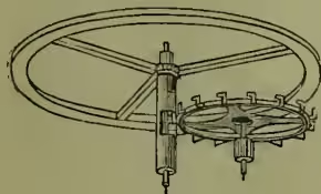
As the vertical or verge escapement, owing to the recoil of the escape-wheel and other causes, is not to be depended on for very great accuracy, attempts were immediately made after the invention of the balance-spring to devise some form of escapement which would give better results. Hooke, Huygens, Hautefeuille, and Tompion introduced improvements, but the first to succeed was made by George Graham, the inventor of the dead-beat escapement in clocks.
This is called the horizontal or cylinder escapement (fig. 10). It was introduced in the beginning of the 18th century, and it is still the escapement used in many foreign watches. The impulse is given to a hollow cut in the cylindrical axis of the balance by teeth of a peculiar form projecting from a horizontal crown-wheel.
Other forms of escapement in high estimation are the lever, the duplex, and the chronometer 'spring-detent' escapement. The lever escapement (invented about 1770 by Thomas Mudge) is the dead-beat escapement (see fig. 4) adapted to the altered conditions of a watch. Fig. 11 shows the form used in most modern English watches. The pallets, P, P, are fixed to a lever, A (pivoted at F), and there is an impulse pin, B (usually a piece of ruby), set in a small disc, C (called the roller), on the axis of the balance.
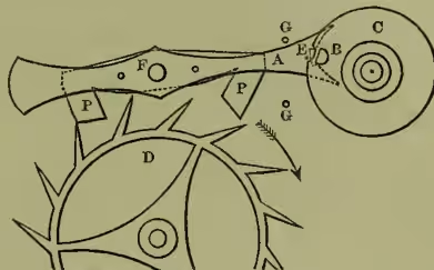
The ruby pin works into a notch at the end of the lever, and the pin and notch are so adjusted that when a tooth of the escape-wheel D leaves the pallet the pin slips out of the notch, and the balance is detached from the lever during the remainder of its swing; whence the name detached lever escapement, originally applied to this arrangement. On the balance returning, the pin again enters the notch, moving the lever just enough to allow the tooth next in order to escape from the dead face of the pallet on to the impulse face; then the escape-wheel acts upon the lever and balance; the tooth escapes, and another drops upon the dead face of the pallet, the pin at the same time passing out of the notch in the other direction, leaving the balance again free. This arrangement is found to give great accuracy and steadiness of performance. A safety pin, E, on the lever, prevents the wheel being unlocked, except when the impulse-pin is in the notch of the lever. Two banking-pins, GG, keep the motion of the lever within the desired limits.
In the duplex escapement (invented about 1780) the escape-wheel has two sets of teeth, hence the name. One set, something like the lever-wheel (fig. 11), lock the wheel by pressing on the balance staff, and the other, standing up from the side of the rim of the wheel, give impulse to the balance. It is rarely used now.
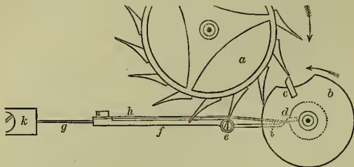
The chronometer spring-detent escapement was invented in principle by Le Roy about 1765, and perfected by Earnshaw (who also invented the cylindrical balance-spring) and Arnold about 1780. It is shown in fig. 12; a is the escape-wheel, which has fifteen teeth; b, the impulse-roller, fixed on the same staff as the balance; c, the impulse-pallet; d, discharge-pallet; e, locking-pallet—all the pallets are of ruby or sapphire; f, the blade of the detent fixed at h by its spring g; and h, the gold-spring. In the fig. a tooth of the escape-wheel is caught on the locking-pallet; the discharge-pallet (carried round by the roller in the direction of the arrow), by pressing on the end of the gold-spring, which in turn presses on the horn of the detent i, bends the detent enough to allow the tooth to escape from the pallet. The escape-wheel, being released, overtakes the impulse-pallet and drives it on till their paths diverge and they separate. The wheel is again brought to a stand by the locking-pallet of the detent, which, on being released by the discharge-pallet, has sprung back to its original position. The roller, having made its vibration, is brought back by the spring. In the return the discharge-pallet forces itself past the end of the gold-spring, the impulse-pallet clears the teeth of the escape-wheel, and the balance goes on till the momentum is exhausted, when the spring induces another vibration, the wheel is again unlocked, and the impulse-pallet gets another blow. By receiving impulse in one direction and unlocking at every alternate vibration only, the chronometer-balance is more thoroughly detached than any other. It is very delicate, however, and, though the most perfect known, it cannot stand rough usage, and is not so suitable for ordinary pocket-watches as a good lever. At sea the chronometer is hung in Gimballs (q.v.), so as to be always horizontal whatever the motion of the vessel.
In watches, even more than in clocks, variations of temperature, unless provided for, produce variations in the rate of going. A rise in the temperature makes the balance expand, and therefore augments its moment of inertia. It diminishes the elasticity of the spring; and the time of vibration of the balance, which depends upon the moment of inertia directly, and upon the elastic force of the spring inversely, is increased—the watch, that is, goes more slowly. A fall in the temperature is attended by opposite results, the watch going more rapidly than before. Compensation can obviously be made in either of two ways—by an expedient for shortening the effective length of the balance-spring as the temperature rises, so as to increase the elastic force of the spring; or by an expedient for diminishing the moment of inertia of the balance as the temperature rises, so as to correspond to the diminution of the force of the spring. The first method was that made use of by John Harrison (q.v.) in his chronometer, and it depended on a laminated bar of brass and steel fixed at one end, called a compensation curb; the free end carries two curb pins, which embrace the balance-spring, and, as the bar shrinks and expands, regulate the length of the spring. It is never used now. An adaptation of the other method, invented in 1782 by John Arnold, and improved by Thomas Earnshaw, is that which is always employed now.
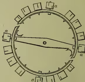
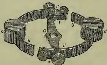
Fig. 13 shows the form employed for marine chronometers, and fig. 14 that for pocket chronometers and watches: t, a, t' (fig. 13) is the main bar of the balance; and t, b, t', b' are two compound bars, of which the outer part is of brass and the inner part of steel, carrying weights, c, c', whose position may be shifted to or from the fixed end, according as the compensation is found on trial to be less or more than is desired. Brass expands more with heat and contracts more with cold than steel; consequently, as the temperature rises the bars with their weights, being fixed at one end to the main bar, bend inwards at the free end, and so the moment of inertia of the balance is diminished; as it falls they bend outwards, and the moment of inertia is increased; and of course the diminution or the increase must be made exactly to correspond to the diminution or increase in the force of the spring. The screws, d, d', fitted to the fixed end of each of the compound bars are used for bringing the chronometer to time; sometimes the smaller ones are dispensed with. In fig. 14 the principle is the same: a, a, a, a are the time screws (equally distributed in the watch-balance); the others are for compensation, and their positions may be shifted or larger ones substituted if necessary.
The modern marine chronometer is just a large watch fitted with all the contrivances which experience has shown to be conducive to accurate time-keeping—e.g. the cylindrical balance-spring, the detached spring-detent escapement, and the compensation-balance. Harrison's chronometer, mentioned above, was the first, and was completed after many years of study in 1736. For a description, see British Horological Journal, vol. xx. page 120. After many trials and improvements, and two test voyages to America, undertaken for the satisfaction of the commissioners, the last of which was completed on the 18th September 1764, the reward of £20,000, which had been offered by government for the best time-keeper for ascertaining the longitude at sea, was finally awarded to him. Harrison made many other inventions and improvements in clocks and watches, including his maintaining spring to the fusee, to keep the works going while being wound; a form of remontoire escapement, &c.
Somewhat later than this several excellent chronometers were produced in France by Berthoud and Le Roy, to the latter of whom was awarded the prize by the Académie Royale des Sciences. Progress was still made in England by Mudge, Arnold, and Earnshaw, to whom prizes were awarded by the Board of Longitude. The subsequent progress of watch-making has been chiefly directed to the construction of pocket-watches on the principle of marine chronometers, and such accuracy has been obtained that the average error is reduced to one second a day.
The compensation of an ordinary balance chronometer cannot be made perfectly accurate for all degrees of temperature, but only for two points. The explanation of this lies in the fact that, while the variations of elastic force in the spring go on uniformly in proportion to the rise or fall of the temperature, the inertia of the balance varies, not inversely as the distance of its weights from the centre, but inversely as the square of the distance of the centre of gyration from the centre of motion.
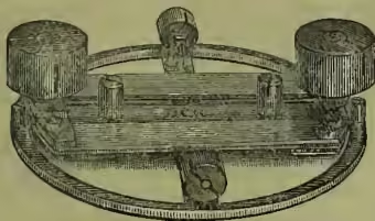
The particular points in the case of any chronometer are matter of adjustment. For instance, one chronometer may be made to go accurately in a temperature of 40°, and also in a temperature of 80°, at other temperatures being not so accurate; another chronometer to go accurately at a temperature of 20° and 60°. It is manifest that the former would be adapted to voyages in a warmer, the latter to voyages in a colder climate. To more fully adjust the compensation certain pieces are fixed to the balance to act in heat or in cold, and this is called auxiliary compensation, and there are at least two or three balances invented of recent years, one of which is shown in fig. 15, which are practically self-adjusting for the ordinary range of temperatures to which marine chronometers are subjected. The solution of the problem seems to be in setting the lamine flat instead of vertical, and making the bar also bimetallic.
Apparatus for testing chronometers have been long in use in the observatories at Greenwich and Liverpool. In the latter there is now an extensive apparatus for this purpose, devised by the ingenious astronomer, Mr Hartnup. In a room which is isolated from noise and changes of temperature the chronometers are arranged on a frame under a glass case, so contrived that they may be subjected in turn to any given degree of temperature. The rate of each under the different temperatures is observed and noted, and the chronometers registered accordingly.
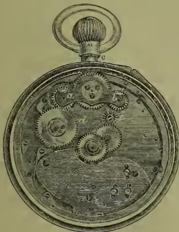
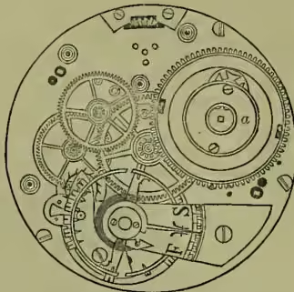
A large proportion of modern watches are made to wind and to set the hands from the pendant. Fig. 16 shows the form of keyless work chiefly employed in English non-fusee watches. The chief part is the three wheels working in the rocking-bar ab, one of which gears with the winding-wheel, d, of the barrel when the rocking-bar, which is capable of a little motion, is in its normal place, as in the fig. A contrate wheel is fixed on the end of the winding-button c, and by its means, when the button is turned, the train is set in motion and the barrel wound. When the hands are required to be set, a push-piece in the case bearing on the end, b, of the rocking-bar is pressed by the finger, taking the rocking-bar wheels out of gear with the winding, and putting them in gear with the hand-wheels at e. The hands push-piece being let go, the train returns to its normal position. The use of the fusee being attended with some amount of complication in the keyless mechanism, it is usually dispensed with on this account, and one of the most modern arrangements in an English keyless watch is shown in fig. 17. The barrel, a, is here made to occupy all the height between the pillar (or lower) plate and the top limit of the movement, and all the space between the centre pinion and the balance cock, in order to get a long, thin mainspring; the advantage of which is that there is an abundance of power (much more than is required for a day's going), and only a portion of the spring is used for the ordinary winding for twenty-four hours. This practically insures an adjustment of the motive power as nearly equal to that obtained by the use of the fusee as it is possible to arrive at.
Repeating watches were first made about 1676, the invention being claimed by Daniel Quare, Edward Barlow, and Tompion. They have a striking arrangement very much on the principle of the striking-clock, and on compressing a spring they at any time strike the hours and quarters, and in some cases the minutes. They are very expensive and liable to go out of repair, and repairs are costly. They have nearly gone out of use. For stop-second arrangements to record swift passing events, see CHRONOGRAPH.
In English watches are mostly made at Preston, Liverpool, Coventry, and at Clerkenwell, London, where the division of labour principle is carried out in an extreme degree—many small factories making, for instance, only balances, others springs, others cases, others hands, &c., only that small number who put the works together seeing the complete watch. At Kew Observatory there are arrangements for testing watches, and granting certificates if satisfactory, on payment of a fee. In the United States the manufacture of watches, like that of clocks, is carried on in a much more wholesale manner; the wheels and plates being stamped by machinery, every similar part being exactly alike and interchangeable; and on account of the economy of manual labour, they can be turned out marvellously cheap. Generally the large clock-factories also manufacture watches.
See Thiout l'ainé, Traité d'Horlogerie (1741); Lepaute, Traité d'Horlogerie (1755); F. Berthoud, Traité des Horloges Marines (1773), Histoire de la Mesure du Temps par les Horloges (1802); Thos. Reid, Treatise on Clock and Watch Making (1819); Jürgensen, Principes de la Mesure du Temps (1838); Moinet, Nouveau Traité général d'Horlogerie (1848); Wood, Curiosities of Clocks and Watches (1866); Denison (afterwards known as Sir E. Beckett and then as Lord Grinthalpe), Treatise on Clocks and Watches and Bells (1874; 7th ed. 1883); books by J. F. Kendal (1892) and F. J. Britten (1894); Saunier, Modern Horology (Eng. trans. by Tripplin & Rigg, 1885); Rombol, Enseignement théorique de l'Horlogerie (Geneva, 1889); Britten, Watch and Clock Makers' Handbook (1889); The British Horological Journal (monthly from 1859); La Revue Chronométrique (monthly from 1857).