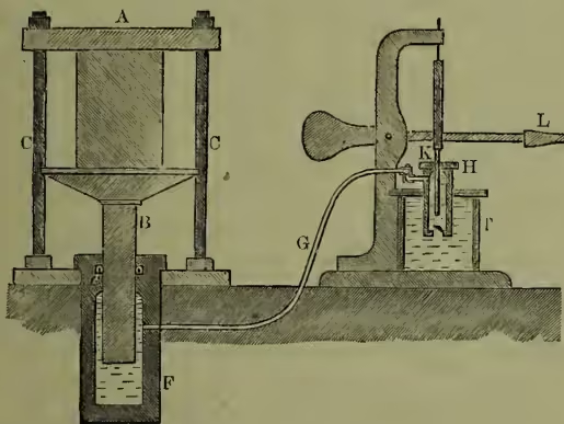
Hydraulic Press. often called Bramah's press, from the inventor, Joseph Bramah (q.v.), depends for its action on the principle that a pressure exerted on any part of the surface of liquid is transmitted undiminished and equally in all directions through the mass (see HYDROSTATICS). The annexed figure represents the essential parts of the machine, minor details of construction being omitted. F is a strong cast-iron or cast-steel cylinder, open at the top; B is a plunger or ram which fits watertight into the cylinder; to prevent leakage a leather ring U-shaped in section is placed in the cavity c; any water trying to leak out forces the two sides of this ring hard against the piston and the side of the cavity, and the greater the pressure the tighter it keeps. This form of packing is now often replaced by an ordinary stuffing-box filled with hemp packing. A pipe, G, leads from the cylinder to a force-pump, H. By means of this pump water can be forced from the tank, T, through the pipe G into the cylinder, thus pushing the plunger or ram, B, upwards. The ram carries on its top a platten or table, on which the bales, &c., to be pressed are placed; the rising of the platten presses them against the entablature or upper plate, A, which is held in position by the columns C. The bale can thus be squeezed to any extent desired.
The power of the press is readily calculated; let the diameters of the pump-plunger, K, and ram, B, be and inches respectively, then any downward pressure on K becomes an upward pressure on B magnified times. Suppose, for instance, that the pressure on K was 500 pounds, and that the diameters are 1 and 10 inches respectively, then the upward thrust would be pounds; very enormous pressures are therefore readily obtained, and in consequence of the slow motion there is extremely little waste of power in friction. It is thus a very efficient mechanism. The pump can either be a hand-pump worked by a lever, L, as in sketch, or it may be worked by a steam-engine, as is the case in the modern powerful presses. The enormous multiplying power of this contrivance has led to its most extensive use; for example, compressing cotton and wool bales, &c., expressing oils, bending iron plates and bars, lifting heavy weights (lifts and hoists), raising into position bridge-girders (hydraulic jacks), &c. Presses of enormous power are now superseding the huge steam-hammers in large steelworks, obviating the unpleasant vibrations and ensuring sounder metal.