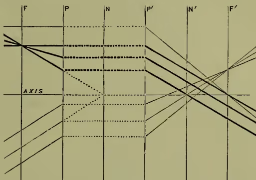
Lenenses. A lens is a piece of glass so shaped as to refract rays of light really or apparently radiating from a point, and make them deviate so as to pass, or to travel on as if they had passed, through another point. Every system of lenses, however complicated and whatever be the mutual distances of the lenses, will, if the whole be centred on a common axis, produce a real image somewhere in front of, or else will appear to produce a virtual image somewhere behind, the last refracting surface. The rays on being traced through the complex combination—e.g. a telescope—undergo numerous deviations: ultimately there is a deviation which might have been equally produced by an equivalent lens; equivalent, however, in no other sense than as producing an equal ultimate deviation, for the image is not formed in the same place as the single 'equivalent lens' would have formed it in. The system of lenses is approximately equivalent in its action to a simple lens plus a determinate shifting of the focus. Hence a simple lens-diagram, modified so as to represent this shifting, will represent the aggregate effect of the most complex system of lenses. When the subject was looked at from this point of view it was found by Gauss, followed up by Listing, that the whole theory of lenses can be treated generally; the most complex system of lenses can be replaced in every case by a region of space traversed by the common axis of the lenses, at right angles to which axis there are six characteristic planes, the relative positions of which to some extent depend upon the refracting media and their forms and mutual distances, but which also present certain invariable properties and mutual relations. These six planes are (1) the incidental focal plane (F, fig. 1); (2) the incidental principal plane, P, and (3) the incidental nodal plane, N; (4, 5, and 6) the refractical principal, nodal, and focal planes, P', N', and F'. The principal properties of these planes are: all pencils of rays converging from any point on the incidental focal plane F (provided in this as in all other cases that no ray is so far from the axis as to give rise to spherical aberration) emerge parallel to one another; conversely, all rays incident parallel to one another come to a focus at a point in the second focal plane F'. An object on one principal plane, P, has an equal-sized image on the other, P'. Any ray appearing on incidence to make for the point where one nodal plane, N, cuts the axis, emerges parallel to its former course, but apparently coming from the corresponding point in the second nodal plane, N'. Rays arriving parallel to the axis pass on emergence through the axial point of the focal plane F'; rays passing through the corresponding point in plane F emerge parallel to the axis. These axial points are the Foci of the lens-system. These properties are diagrammatically shown, with exaggeration of the distances of the rays from the axis, in fig. 1.
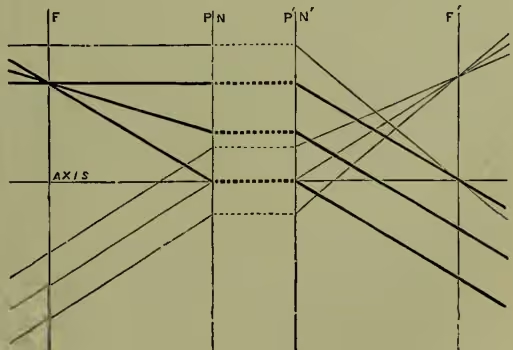
In this diagram the six planes are represented as equidistant; they are generally not so; their position has to be calculated. The calculation (see Pendlebury, Lenses and Systems of Lenses) necessitates the use of standard formulæ involving continued fractions; the physical principle underlying these is that the image (real or virtual) produced by one refracting surface is taken as the object of the next, and so on in succession until the position and deviation of the emergent rays is established. The fixed relations between the mutual distances of these planes are: ; ; and , where is the ratio between the refractive index of the final and that of the original medium. The matter is greatly simplified when, as in the ordinary case, the final and the original media are the same (lens or telescope in air); then , each nodal plane coincides with the corresponding principal plane, and . The diagram takes the form indicated by fig. 2. If we come now to the simplest case, that of a single thick lens in air (fig. 3), the standard formulæ, according to this method, are
In these formulæ is the radius of the A surface, measured towards the centre and towards the right; that
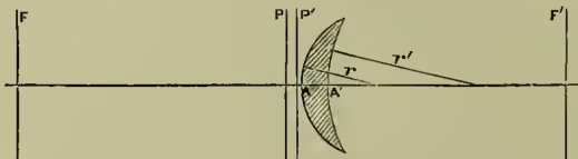
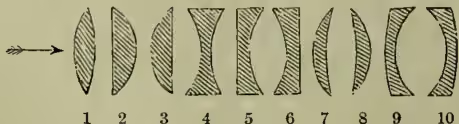
of the surface, measured in the same way; is , the thickness of the lens; is its refractive index as compared with that of the surrounding medium (air) = 1. As an example, let us apply these formulæ to a biconvex lens of crown-glass, : let the radii be inches at and (negative because measured to the left) at ; and let the thickness be 1 inch. Putting these numerical values instead of the letters in the formulæ, we get inches; is 4.69 inches from (to the left of) the A surface. inches; is 4.55 inches from . ; the principal plane is to the right of , inside the lens. ; the second principal plane is to the left of , inside the lens. The two principal planes are therefore both inside the lens, 0.31 inch apart, and are nearer the more curved face of the lens. The distance , between either focus and the corresponding principal plane, is 4.96 inches, and this is the focal distance or the focal length of the lens; this, not the distance between the focus and the centre or the surface of the lens. The two focal distances are equal; hence if we could by reversing the lens make the principal planes exchange places, the action of the lens would be the same in both positions; but this cannot be done with an unsymmetrical thick lens by simply reversing it in its setting, on account of the unsymmetrical position of the planes within the lens. If we take the ten cases in which the lenses are respectively: (1) biconvex ( positive, negative; equiconvex if ); (2) plano-convex ( and ; negative); (3) convexo-plane (, ); (4) biconcave (); (5) plano-concave (); (6) concavo-plane (); (7) convex meniscus ( greater than ); (8) concave meniscus ( numerically greater than ); (9) convexo-concave ( greater than ); (10) concavo-convex ( numerically greater than )—we find, on giving the proper signs to the respective terms in the standard formulæ above, that in lenses with a flat face one of the principal planes coincides with the vertex of the curved surface; that in all double concave and practically in all double convex lenses the principal planes are within the lens itself; that in lenses 7 and 8 the planes lie outside the convex face until the concave face is flattened so far as to draw one of them upon the lens; and that in lenses 9 and 10 the planes lie outside the concave surface until its curvature increases so far as to draw the nearer plane into the lens. We also find that in all simple lenses whose edges are thinner than their centres is negative (i.e. is to the left of ), and the lens makes parallel rays incident upon it to converge upon some point in the opposite focal plane; while in thick-edged lenses is positive and negative, and the planes lie in the order , those rays which were parallel before incidence being divergent on emergence, and holding a course as if they had come from some point on that focal plane which lies on the same side of the lens as the source itself. When the incident rays are parallel to the axis and to each other, on emergence they converge really upon the opposite focus of a thin-edged lens or appear to diverge from the virtual focus of a thick-edged lens.
When the incident rays diverge from a point not on the focal plane they come to a focus at a definite point elsewhere than on the second focal plane.
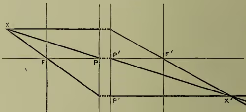
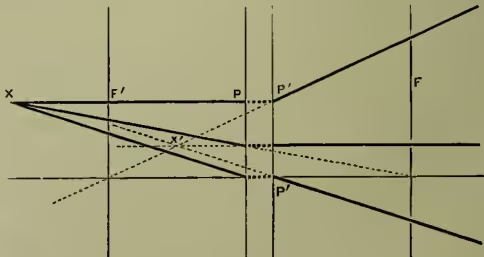
Fig. 5 diagrammatically illustrates this for a convergent lens. A pencil from converges on : the geometry of the figure shows (by similar triangles) that . Hence, if or , the focal length, be written , and the distances and be written and , then, numerically, . Fig. 6 illustrates the same thing for a divergent lens: , or, numerically, .
These equations give, numerically, the relations between and , the distances of the object and the image respectively from the corresponding principal planes and . The general numerical formula which covers these relations is that if and and , being taken as numerically negative in convergent and positive in divergent lenses, then
If an object occupy a plane passing through at right angles to the axis, the corresponding image will (aberration apart) be in a similar plane passing through . Fig. 7 shows rays from three points of an object passing through the nodal points and and emerging parallel to their former courses.
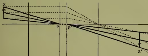
The size of the image is easily seen to be to that of the object as is to . In a convergent lens the image of a distant object is inverted and real; there is a real crossing of rays in the image, and the real image is formed suspended, as it were, in space, invisible from points not in the path of the rays; a screen of card, of ground glass, or of tissue paper may be placed so as to coincide with the real image, which then becomes visible on the screen: if the eye be removed to a sufficient distance in the path of the rays the inverted real image in space itself becomes visible as an object in space between the lens and the observer, an inverted reproduction of the original object; and this inverted copy is, for all distances between the object and the lens exceeding twice the focal length, smaller than the original object, and for all such distances between twice and once the focal length it is greater than it. When the object is placed within the focal distance is less than , and is therefore numerically negative; the image is virtual; no screen will at any place receive an image; but the rays come to the eye as if they had proceeded from a larger object more remote from the lens on the original side of it; whence such lenses are commonly employed as magnifying glasses. Whenever the image formed is a real one the object and the image are interchangeable; an object placed in the position of the real image will produce a real image on a screen placed in the position of the original object. A comparison of fig. 6 with figs. 5 and 7 will show that the virtual image formed by a divergent lens is smaller than the object and is not inverted.
In all these cases the lenses are supposed to have an appreciable thickness. If, however, we assume that the thickness is negligible, the formulæ given above are modified by suppression of all terms containing ; they become simply , or ; and . Whence the principal planes coalesce and blend with the surfaces; and the ordinary lens-formulæ are obtained, in which , the focal distance, means half the distance between the two focal points. The result is only approximate, as the numerical example already discussed will show when treated in this way. There ; ; ; whence inches, and the distance between the two foci is inferred to be 9.6 inches; whereas we have previously seen this distance (including ) to be 10.24 inches. On the assumption now made, a lens is reversible; for in the formula we find that when the radii exchange places both change their signs, the result being the same. On giving the proper signs and numerical values to and in the simplified formula, it is easy to arrive at the numerical value of for a lens of any form: if be negative, the lens is convergent (thin-edged); if positive, it is divergent. Then, having been found, the relation between , , and can be found by giving and their proper signs and numerical values in the general equation . If we find negative we infer a virtual, if positive a real image. For example, a crown-glass lens (), biconcave; inches; ; ; , a divergent lens. Object at distance, say, inches; inches; a virtual image, smaller than the object in the ratio of 3.92 to 196, or one to fifty. Again, a similar lens, but biconvex; ; ; inches, a convergent lens. Let the object be at 204 inches; ; ; inches—a real image, smaller in the ratio of 4.08 to 204, or one to fifty. Let the object be at inches; and the image is virtual, enlarged in the ratio of , or eightfold, by the use of the lens as a magnifying glass. The nearer the object to the focus the greater the enlargement. To make the image equal in size to the object, must be equal to ; then ; and . With a convergent lens adjust the positions so that the object and its image on a screen are of the same size; then they are at a distance of four times the focal length from each other. In this way, neglecting the thickness, the focal length of a convergent lens may be ascertained. It may also be ascertained by means of an object (spider-threads or a piece of muslin), and a telescope focussed for a very distant object; direct the telescope towards the spider-threads; interpose the lens to be examined; shift it until the spider-threads are distinctly seen in the telescope; the spider-threads are then in the focus of the lens, which causes the rays from them to pass parallel into the telescope. A divergent lens has its focal length measured by conjoining it with a convergent one, which neutralises or overbalances its effect: if be the focal length of the convergent combination, that of the convergent lens, and (unknown) that of the divergent lens, ; the deviation produced by a lens is inversely proportional to its focal length, and the equation states the proposition that the convergence produced by the one, together with the divergence produced by the other, is equal to the convergence produced by the combination.
When the light from an object is mixed the refractive index differs for each colour; the distance of the image is different for each spectral colour; thus a series of images are formed behind one another, the violet in front and the red behind; those behind are larger and overlap, and therefore the image appears to have a spectral fringe of colour, red outside. To prevent this chromatic aberration images of two or more colours, say the blue and orange, should be brought to the same plane and be of the same size; this is done for two colours or wave-lengths by combining a crown-glass convergent of excessive power with a flint-glass divergent lens; the curvatures are so chosen that the spectral dispersion produced by the one is compensated by the re-combination produced by the other; but, since in the two materials the refractions and dispersions are not proportional to one another, there remains a balance of deviation accomplished without chromatic dispersion. Newton thought dispersion and deviation to be always proportional to one another, and achromatism therefore impossible; Dr Hall in 1733 found this not to be so, and made achromatic lenses, but did not publish his discovery. Dollond in 1757 first introduced achromatic lenses. When two colours are achromatised there is still some chromatic aberration as regards the rest; to bring a greater number of colours to the same focus requires a greater number of refracting surfaces.
In all the preceding it has been assumed that the lenses are narrow, or that the pencils of rays fall on the centre of the face, and that the objects are small. When the object is viewed by the lens under a wide angle a plane object gives an ellipsoidal, paraboloidal, or hyperboloidal image, which, when real, cannot be wholly received in focus upon a plane screen; and oblique rays fail to converge upon precise points, and hence, even on a screen so curved as to receive the oblique pencils of rays when at their greatest concentration, the image will not be equally distinct all over. Further (spherical aberration), if the lens be too wide, or its curvature too considerable, the rays falling on different zones of the lens are, as it were, received by prisms of different angle; those incident on exterior zones are more sharply refracted than those nearer the axis, and their focus lies at a point some distance nearer the lens than the geometrical focus (longitudinal aberration), and the image is thus distorted, so that the image of a square object formed by a single convex lens appears to be drawn out at the corners, and that formed by a concave lens appears to have its corners squeezed in; besides which there is blurring, for pencils incident near the edge have their foci not even on the axis, but short of it. To remedy these defects, which cannot all be thoroughly dealt with at the same time, various 'aplanatic' combinations of lenses of different curvatures have to be employed to build up a compound 'equivalent lens;' and these combinations have to be adapted to the particular purpose for which the lens-system is to be used (see Parkinson's and Coddington's Optics). The property of refracting light-rays possessed by lenses necessarily applies also to heat and actinic rays; whence the use of lenses as burning-glasses (in which parallel heat-rays from the sun are brought to a focus at the principal heat-focus of the lens) and photographic lenses. The heat-focus is somewhat farther, the actinic focus somewhat nearer to the lens than the light-focus is; but, by the application of the principles of correction for chromatic aberration, the visual and the actinic forms are, in the last case, made to coincide.