Steam-engine. Steam-engines in their infancy were known as 'fire' (i.e. heat) engines; and in point of fact the older term is the more correct, because the water or steam is only used as a convenient medium through which the form of energy which we call heat is made to perform the required mechanical operations. In modern engines sufficient heat is added to the steam to raise it to a very high pressure, and the excess of this pressure over the pressure opposed to it (either atmospheric pressure or the still lower pressure in a condenser) is both the cause and measure of the work done by the engine. In earlier machines, however, the steam was raised only to atmospheric pressure, and admitted into the engine only to be at once condensed by a jet of cold water. The excess of the atmospheric pressure above the pressure in the partial vacuum caused by the condensation was then the direct cause of work. Engines of this kind were called atmospheric engines.
The invention of steam as a moving power is claimed by various nations; but the first extensive employment of it, and most of the improvements made upon the steam-engine, the world indisputably owes to Britain and the United States.
Among the first notices we have in England of the idea of employing steam as a propelling force, is in The Art of Gunnery (1647), by Nat. Nye, mathematician; in which he proposes to 'charge a piece of ordnance without gunpowder,' by putting water instead of powder, ramming down an air-tight plug of wood, and then the shot, and applying a fire to the breach 'till it burst out suddenly.' But the first successful effort was that of the Marquis of Worcester. In his Century of Inventions, the manuscript of which dates from 1655, he describes a steam-apparatus by which he raised a column of water to the height of 40 feet. This, under the name of 'Fire-waterwork,' appears actually to have been at work at Vauxhall in 1663-70. Sir Samuel Morland in 1683 submitted to Louis XIV. a project for raising water by means of steam, accompanying it with ingenious calculations and tables. The first patent for the application of steam-power to various kinds of machines was taken out in 1698 by Captain Savery. In 1699 he exhibited before the Royal Society a working model of his invention. His engines were the first used to any extent in industrial operations; they seem to have been employed for some years in the drainage of mines in Cornwall and Devonshire. The essential improvement in them over the older ones was the use of a boiler separate from the vessel in which the steam did its work; one vessel in all former engines had served both purposes. He made use of the condensation of steam in a close vessel to produce a vacuum, and thus raise the water to a certain height, after which the elasticity of steam pressing upon its surface was made to raise it still further in a second vessel.
In all the attempts at pumping-engines hitherto made, including Savery's, the steam acted directly upon the water to be moved without any intervening part. To Denis Papin (q.v.), a French physicist, is due the idea of the piston. It was first used by him in a model constructed in 1690, where the cylinder was still made to do duty also as a boiler; but in an improved steam-pump invented about 1700 he used it as a diaphragm floating on the top of the water in a separate vessel, or cylinder, and the steam, by pressing on the top of it, forced the water out of the cylinder at the other end.
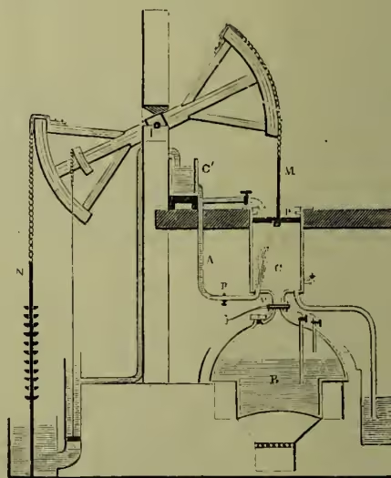
The next great step in advance was made about 1705 in the 'atmospheric' engine, conjointly invented by Newcomen (q.v.), Cawley, and Savery. This machine (fig. 1) held its own for nearly seventy years, and was very largely applied to mines. In it the previous inventions of the separate boiler and of the cylinder with its movable steam-tight piston are utilised, although in a new form. The 'beam,' which has ever since been used in pumping-engines, was used for the first time, and for the first time also the condensation of the steam was made an instantaneous process, instead of a slow and gradual one. Newcomen's engine was chiefly used, like all former steam-engines, in raising water. To one end of a beam moving on an axis, I, was attached the rod, N, of the pump to be worked; to the other the rod, M, of a piston, P, moving in a cylinder, C, below. The cylinder was placed over a boiler, B, and was connected with it by a pipe provided with a stopcock, V, to cut off or admit the steam. Suppose the pump-rod depressed, and the piston raised to the top of the cylinder—which was effected by weights suspended at the pump-end of the beam—the steam-cock was then turned to cut off the steam, and a dash of cold water was thrown into the cylinder by turning a cock, R, on a water-pipe, A, connected with a cistern, C'. This condensed the steam in the cylinder, and caused a vacuum below the piston, which was then forced down by the pressure of the atmosphere, bringing with it the end of the beam to which it was attached, and raising the other along with the pump-rod. The cock was then turned to admit fresh steam below the piston, which was raised by the counterpoise; and thus the motion began anew. The opening and shutting of the cocks was at first performed by an attendant, but subsequently a boy named Humphrey Potter (to save, it is said, the trouble of personal superintendence) devised a system of strings and levers by which the engine was made to work its own valves. In 1717 Henry Beighton, an F.R.S., invented a simpler and more scientific system of 'hand-gear,' which rendered the engine completely self-acting. During the latter part of the time that elapsed before Watt's discoveries changed everything Smeaton brought Newcomen's engine to a very high degree of perfection. As the result of study and experiment he made many improvements in it, in the form of the boiler, the proportions of the cylinder, &c. It was he, too, who invented the cataract, a very ingenious self-acting valve arrangement, which is still used in Cornish engines. In 1725 Leupold invented an engine in which steam of a higher pressure than that of the atmosphere was employed in the cylinder, but his engine possessed defects that prevented its practical use.
The next essential improvements on the steam-engine were those of Watt, which began a new era in the history of steam-power. The first and most important improvement made by Watt was the separate condenser, patented in 1769. He had observed that the jet of cold water thrown into the cylinder to condense the steam necessarily reduced the temperature of the cylinder so much that a great deal of the steam flowing in at each upward stroke of the piston was condensed before the cylinder got back the heat abstracted from it by the spurt of cold water used for condensing the steam in the cylinder. The loss of steam arising from this was so great that only about one-fourth of what was admitted into the cylinder was actually available as motive-power. Watt therefore provided a separate vessel in which to condense the steam, and which could be kept constantly in a state of vacuum, without the loss which arose when the cylinder itself was used as a condenser. This device, which now looks simple enough, was the greatest of Watt's inventions, and forms the foundation of his fame. His genius was such that in a few years he changed the steam-engine from a clumsy, wasteful, almost impracticable machine into a machine practically the same as that which we now have. The principal improvements since his time have been either in matters relating to the boiler; in details of construction consequent on our increased facilities, improving machinery, and greater knowledge of the strength of materials; in the enlarged application of his principle of expansive working; or in the application of the steam-engine to the propulsion of carriages and vessels. His principal inventions were: (1) The condensation of steam in a vessel separate from the cylinder, so as to avoid the cooling of the latter; (2) the use of a pump, called an 'air-pump,' to withdraw the condensed water and mixed steam and air from the condenser; (3) the surrounding of the cylinder with a steam-jacket, in order to prevent loss of heat from condensation (these three, with others, were included in the specification of 1769); (4) the use of the steam expansively in the way explained further on in this article (this was invented before 1769, but not published till 1782); and (5) the now universally used double-acting engine, and the conversion of the reciprocating motion of the beam into a rotary motion by means of a crank (both these were invented before 1778, the engine being patented in 1782, but the crank having before that date been pirated and patented by another). In 1784 Watt also patented and published his parallel motion, throttle-valve, governor, and indicator; all four of which are in substance still used.
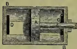
The common mode of employing steam in an engine is by causing it to press alternately on the two surfaces of a movable diaphragm or piston enclosed in a fixed, steam-tight, cylindrical box. In fig. 2 A is the piston and B a section of the box.
The piston, by means of a rod, E, passing through the end of the box, is made to communicate motion to the rest of the machinery. The steam is first admitted to one end of the cylinder through an opening or 'port,' D, and forces the piston along to the other end. The current of steam from the boiler is then allowed to pass into the other end of the cylinder through the opening C, and forces the piston back again to its original position, and so on. But it is obvious that while this return-motion is going on the steam previously admitted at D must be allowed some exit, or the piston could not be forced back. The manner of this exit constitutes the difference between the two principal classes of engines, according as the steam is allowed simply to rush out into the atmosphere or is conducted into a separate vessel, and there 'condensed.'
The simplest way in which steam can be used in a cylinder is at the same time the most wasteful. It consists in filling each end of the cylinder alternately full of steam direct from the boiler, and having the full boiler pressure, and thus forcing the piston along in exactly the same way as that in which it would have to be forced were water the fluid used instead of steam. If we imagine the cylinder to have a capacity of 7 cubic feet, then, if it be filled entirely with steam from the boiler at 60 lb. absolute pressure, it will contain (about) one pound-weight of steam. The total heat in this pound of steam (above 32° F.), as given in the table, is equivalent to 1171 thermal units in excess of that possessed by a pound of water at 32° F. When the piston, A, has reached the end of its stroke, the steam contained in the cylinder is thus in itself a great storehouse of work, for each of these thermal units is equivalent to 772 'foot-pounds' of mechanical energy, so that the total represents about 904,000 foot-pounds, of which we shall see later on only about has been utilised during the stroke, leaving untouched. Instead of making any attempt to utilise this huge balance, at the moment when the cylinder is full of steam the opening C is put into communication with the boiler, the opening D with the atmosphere, and the steam immediately rushes out of the cylinder, and dissipates its contained energy through the air. Although the steam, when allowed to go into the atmosphere, is immediately reduced to the pressure corresponding to the temperature of the air (which in ordinary cases would be only a fraction of a pound per square inch), still the full pressure of the atmosphere itself will always be acting on the back of the piston during its stroke, and therefore, to find the force with which the piston is being pushed along, we must subtract that pressure from the steam-pressure. On the one side of the piston will be the atmosphere with its uniform pressure of nearly 15 lb. per square inch, and on the other side the steam-pressure of 60 lb. The effective pressure thus will be 60 - 15, or 45 lb. per square inch only.
Let us now consider the somewhat more economical case of an engine in which the steam is first used as described above, but afterwards, instead of being allowed to pass into the atmosphere, is conducted through a pipe into a closed vessel and there condensed. Condensation consists in the subtraction from steam of a portion of its sensible heat. This reduction of temperature has a double effect on the steam: (1) the cooling and liquefaction of a part of it; and (2) the reduction of the rest to the pressure corresponding to the reduced temperature. It is not possible to do one of these things without the other. What is commonly called 'vacuum' simply means pressure less than the atmospheric pressure; and, in the case of steam-engines, a vacuum generally implies a pressure of between 2 and 3 lb. per square inch—i.e. from a seventh to a fifth of the ordinary pressure of the air. The most common way of condensing steam is by bringing it into contact either with a jet of cold water or with surfaces kept continually cool by a current of water. In either case, directly the steam is brought into contact with the water or cooling surface, it transfers to it the larger portion of its sensible heat. During this process the greater part of the steam is liquefied, and the remainder retains only such a pressure as corresponds to its greatly reduced temperature.
The advantages possessed by a condensing over a non-condensing engine will now be obvious. When the piston is being forced from C to D by steam entering through C, the force on the back of the piston resisting its motion in that direction, instead of being equal to the pressure of the atmosphere, is only the pressure of the steam in the condenser, or about 2 lb. per square inch. The net effective force is therefore 60 - 2 or 58 lb. instead of 60 - 15 or 45 lb.
We have supposed that our cylinder when full of steam contained just one pound-weight at 60 lb. pressure. Let us now find out how much useful work this pound of steam has done for us, and we will then show how the same weight may be made to do a great deal more, by utilising more of its great store of heat. Let us suppose that the area of the cylinder is 2 square feet, while its length (the stroke of the piston) is 3½ feet. It will thus have a capacity of 7 cubic feet, as before assumed. In the first case described we should have a pressure of 45 lb. per square inch exerted on an area of 288 square inches through a distance of 3½ feet. This is equal to 45,360 foot-pounds of work. In the second case we have a pressure of 58 lb. per square inch on the same area and through the same distance. This is equal to 58,464 foot-pounds of work, or about of the total heat supplied by the fuel. (For simplicity's sake we have here assumed that the water in the boiler has to be raised from 32° to 292°, and evaporated at that temperature. If the water were supplied at 212°, then the work done would be about instead of of the total heat.) We may now proceed to examine the way in which the same weight of steam, generated by the consumption of an identical weight of fuel, may be made to perform many times more work by 'working expansively.'
One of the properties possessed by steam, in common with all other gases, is a tendency to expand indefinitely; its pressure varies nearly inversely as its volume. For simplicity's sake we shall here assume that steam is a perfect gas, and follows Boyle's law, the pressure varying exactly inversely as the volume. If then we have a cylinder of the same area as before, but of twice the length, but only intend to admit 1 lb. of steam into it at a time, it will be necessary, when the piston has travelled 3½ feet of its stroke, to shut the entrance valve, so as to prevent more steam entering; this is called 'cutting off' the steam. The piston, however, still continues its motion in the same direction as before, propelled by the internal separative energy among the particles of steam. But as it is pressed forward the space occupied by the steam is always increasing, and its pressure always decreasing in proportion, until at length, when the piston has reached the end of its stroke, the steam occupies exactly double its original volume—viz. 14 cubic feet, and is reduced in pressure to half its original pressure—viz. to 30 lb. per square inch. We have thus during the first half of the stroke a constant pressure on the piston of 60 lb. per square inch, and during the second half a pressure gradually decreasing from 60 to 30 lb. The mean pressure during this second half of the stroke will be found on calculation to be almost exactly 40 lb. Let us now, in the same way as before, see what work we have been able to get out of our pound of steam by expanding it in this way. In the first half of the stroke we have 58,464 foot-pounds of work exactly as before, and then we have in addition a mean pressure of 40 - 2, or 38 lb. per square inch, exerted over 288 square inches for a distance of 3½ feet. This equals 38,304 foot-pounds, making a total of 96,768 foot-pounds of work obtained from the steam which only gave us 58,464 before. The economy of working expansively, however, goes much further than this. If the cylinder had been four times its original length, and the steam had been cut off at the same point as before (which would then be quarter instead of half stroke), we should have obtained from the 1 lb. of steam about 144,000 foot-pounds of work. If we had gone still further and expanded the pound of steam into eight times its original volume, we should have obtained about 180,000 foot-pounds of work, which is more than three times as much as at first. (In actual working, owing to various causes—such as imperfect action of the valves, radiation from the cylinder, bad vacuum, &c.—the work obtained from the steam is not more than '65 to '75 of that given in this paragraph.) All modern engines are worked more or less on this principle of expansion, and the general tendency seems to be every year to adopt higher initial pressures and (within certain limits) larger ratios of expansion.
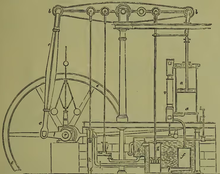
Fig. 3 represents Watt's 'double-acting' condensing engine. By 'double-acting engine' we mean an engine such as was sketched in fig. 2, in which the steam acts on both sides of the piston instead of only on one, as in Newcomen's engine. Watt's engine, though not of the form now generally used, contains all the parts now considered essential. The steam from the boiler passes direct to the valve-chest, v, which is simply a long box attached to the cylinder, a. In this chest are placed valves, which are so regulated as to open communication between the boiler, cylinder, and condenser, in such a way that when the top of the cylinder is open to the boiler the bottom communicates with the condenser, and vice versa. When the steam has done its work it passes out through closed in another cylinder, and the annular space or 'jacket' between them filled with steam from the boiler, principally with the object of preventing liquefaction in the cylinder, which is fatal to economical working. The openings for the entrance and discharge of the steam (shown at C and D in fig. 2) are both called ports. the bent pipe into the condenser, f, where it is met by a jet of water (not shown in the engraving), and condensed, as before explained; g is a pump called the air-pump, which continually draws away the contents of the condenser, and discharges them into a cistern, h, called the hot well. A small force-pump, j, draws part of the water from this cistern, and sends it back again to the boiler, there to be reconverted into steam, while the rest of the water is allowed to run to waste. A suction-pump, k, supplies water to the large tank round the condenser, and also for the condensing jet. Inside the cylinder are the piston and the rod (called the piston-rod) connecting it with the beam, bb. In Newcomen's engine the rod had only to pull the beam down, and not to push it up; it could, therefore, be connected to it by a chain, as shown in fig. 1. In the double-acting engine the piston-rod is required both to pull and to push the beam, so that the chain is no longer admissible. It is obvious that as the head of the rod must move in a straight line, while every point in the beam describes an arc of a circle, the two cannot be rigidly connected. Watt invented the arrangement of rods shown in fig. 3, by which the piston-rod head is always guided in a straight line, while the end of the beam is left free to pursue its own course. This is called a 'parallel motion.' The end of the beam farthest from the cylinder is connected by a rod, cc, called a connecting-rod, to the crank, l, which is firmly fixed on the shaft; and by this means the reciprocating motion of the beam is converted into the rotary motion of the 'crank-shaft,' r. The governor, m, and the flywheel, ee, will be explained further on.
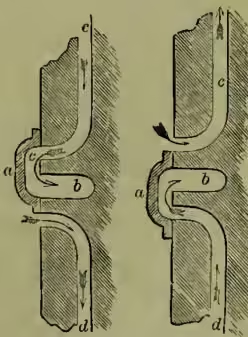
The cylinder and its piston are both made of cast-iron. The former is very accurately bored in a special machine, and ought always to be covered outside with non-conducting material to prevent radiation of heat. It is frequently en- closed in another cylinder, and the annular space or 'jacket' between them filled with steam from the boiler, principally with the object of preventing liquefaction in the cylinder, which is fatal to economical working. The openings for the entrance and discharge of the steam (shown at C and D in fig. 2) are both called ports. The valve or valves which regulate the admission of steam to the cylinder vary very much in construction and design. In ordinary engines one valve, called a slide-valve, does the whole work for each cylinder in a way which we shall explain by the aid of fig. 4. This figure shows the valve in two positions—viz. those corresponding to the times when the piston is at the middle of its stroke, going in the two different directions; c and d are the ports, the ends of which are denoted by the same letters in fig. 2; b is the 'exhaust port,' or opening through which the steam passes to the condenser; and a is the slide-valve working inside the steam-chest (the latter not shown). The sketch to the left shows the position of the valve when the piston is moving upwards. The steam enters the cylinder through d, as shown by the arrows, while the steam in the other end is free to rush out by c under the valve, and through b into the condenser. By the time the piston has reached the same position, going in the opposite direction, the valve is in the position shown in the right-hand sketch, and the motion of the steam is exactly reversed. The valve in fig. 4 opens one port at the same moment as it closes the other. This corresponds to entirely non-expansion working. In order to 'cut off' the steam before the end of the stroke the breadth of the ends of the valve must be increased. This is called giving 'tap' to the valve. When it is desired to 'cut off' the steam earlier than half-stroke, a separate valve, called an expansion valve (of which there are innumerable varieties), is generally used. The rod to which the piston is attached is called the piston-rod, and the rod which actually drives the crank the connecting-rod. In
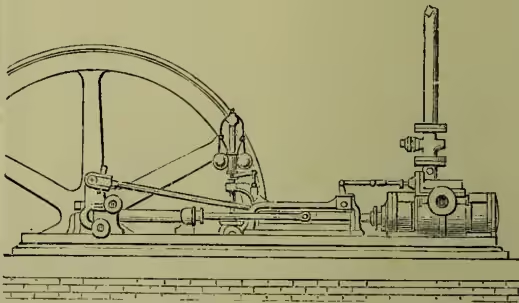
Watt's engine and similar machines these are connected to opposite ends of a beam, but in the common type of engine shown in fig. 6 (below) the two rods are directly attached. The flywheel is a large wheel fixed on the crank-shaft, and having a very heavy rim. As it revolves this contains, stored up in itself, a great quantity of energy, and so equalises the motion of the shaft, and by restoring some of the energy enables the engine to pass the 'dead-points,' or points at which the connecting-rod and crank are in a line. The condenser is simply a cast-iron box of any convenient shape.
The water for condensing the steam is introduced into it in a jet in such a way that its particles mix with the steam at once on entering, and condense it almost instantaneously.
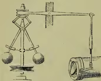
The governor, shown in fig. 5, is an ingenious application by Watt of mechanism long used in water-mills. Its object is to make the engine to cause to revolve fixed on it. Two levers are pivoted on a pin near the top of the spindle, and at the lower end of each is fixed a heavy cast-iron ball. When the engine is running at its proper speed the balls revolve with the spindle in the position shown; but if that speed be increased the centrifugal force causes them to fly outward, and consequently upward; and conversely, if it be decreased they fall downward towards the centre. At the upper end of the spindle is a system of levers, by which it will be seen that the raising of the balls tends to close, and their lowering to open, the throttle-valve at the right of the engraving. The valve in the figure is simply a disc of metal placed in the steam-pipe near the cylinder, but a great many other types of valve—more expensive but more efficient—are now used for the same purpose. The further this valve is opened the greater the amount of steam admitted to the cylinder, and vice versa, and so the tendency of the engine to alter its speed arising from causes extraneous to itself is just balanced by the alteration made in the amount of steam admitted through the throttle-valve. In order that economy as well as regularity of working may be attained, it is in many cases necessary that the governor should be so arranged as to control the ‘cut-off’ instead of throttling the steam as in the figure.
The ‘Cornish’ engine, so called from the fact that it is principally used in the Cornish mines, resembles Watt’s engine in general appearance. Like Newcomen’s engine it is used exclusively for pumping and has no rotary motion, and it is virtually single-acting; but, unlike his, the steam-pressure and not that of the atmosphere actually does the work. Cornish engines are fairly economical of steam, but are very costly and extremely heavy and unwieldy.
Engines in which the piston-rod and connecting-rod are directly attached are called direct-acting engines, of which the horizontal engine shown in fig. 6 is the most common type. For all ordinary purposes direct-acting engines are rapidly superseding every other form. They possess the merit of having great simplicity and few working parts, and of all these parts being easily accessible to the engine-driver; and at the same time any required degree of economical working can be obtained in them as well as in any other form. They were at first only used as non-condensing (or so-called ‘high-pressure’) engines, but are now as frequently made with a condenser attached.
Two other forms of direct-acting engines have been much used in their day, but are now being rapidly abandoned except under special circumstances; these are called respectively the ‘oscillating’ and the ‘trunk’ engine. In the former (which has rarely been used except for marine engines) the crank-shaft is above the cylinder, the piston-rod head is attached to the crank-pin, and the connecting-rod is dispensed with by allowing the cylinder to oscillate on large hollow centres called trunnions, and so to adapt itself to the various positions of the crank-pin. In the ‘trunk’ engine the piston-rod becomes a hollow cylinder or trunk, large enough to allow the connecting-rod to vibrate inside it. The latter is then attached at one end to the crank-pin as usual, and at the other to a pin fixed in the piston.
Direct-acting engines are now made to run at extremely high speeds, for driving dynamos, &c. direct. For this purpose they are made single-acting only, so that the steam-pressure tends always to keep the working surfaces pressed together, and there is none of the shock and noise found in ordinary engines where the direction of pressure is reversed at each stroke. The first successful machine of this type was Mr Brotherhood’s ‘three-cylinder’ engine, of which an immense number are in use. Of late years Mr Willans, in his ‘central valve’ engine, has added an exceptional degree of economy in steam to the other advantages of the single-acting type. Willans’ engines are now very commonly used in the more important electric lighting stations in Britain for the direct driving of dynamos, and have given most satisfactory results. An immense amount of ingenuity has been expended in devising engines in which the rotary motion of the shaft is obtained directly from the piston without the intervention of reciprocating parts. These machines are called rotary engines; they have never come into general use, and most of them have been defective in construction as well as founded on a dynamical misconception.
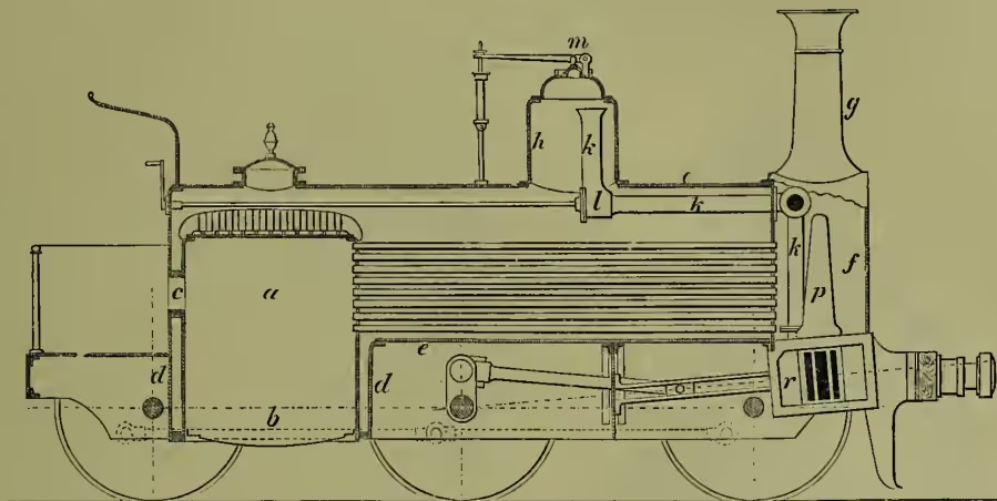
In locomotive engines it is necessary that the whole machinery should be compressed into the smallest possible bulk, and this necessity is the cause of their principal peculiarities. The engine itself is much the same as an ordinary horizontal engine, and has two cylinders placed side by side near the front of the locomotive. These cylinders are sometimes placed inside the main framing, which runs the whole length of the engine, and sometimes outside it, each plan having certain advantages. Fig. 7 is an outline section of an ‘inside cylinder’ goods-locomotive belonging to the Midland Railway Company. At the back of the locomotive is the firebox, a, the bottom of which is formed by the grate, b. Fuel is introduced by the door, c. The firebox is enclosed in a casing, d, and the space between is filled with water. This space communicates freely with the barrel, e, e, of the boiler, a long wrought-iron or steel cylinder. From the back of the firebox numerous small tubes traverse the boiler (through the water) to the smoke-box, f, and conduct the products of combustion to the chimney, g. The steam-pipe, k, is led away from near the top of the dome, h, and fitted with a regulator valve, l. At m are a pair of spring safety-valves. Both cylinders discharge their steam through the vertical blast-pipe, p, and by this means a sufficient draught is caused, notwithstanding the small height of the chimney. The cylinders, r, are placed in the bottom of the smoke-box, and partly enclosed in it.
In all marine engines, except the very smallest, two cylinders are used, working cranks at right angles to each other, so as to equalise the motion as far as possible, it being almost impossible to use a flywheel of sufficient weight for that purpose on board ship. The form originally known as the 'steam-hammer' engine (from the resemblance of early models to Nasmyth's steam-hammer), or some modification of it, is now almost universally adopted. They are direct acting, but the cylinders are inverted, and placed right above the propeller shaft. Two of the greatest improvements in the modern steam-engine—the surface-condenser and the compound engine—have been brought to perfection chiefly in connection with marine engines here. In the surface-condenser the steam is condensed by contact with the exterior surface of a great number of small tubes, through the interior of which a current of cold sea-water is kept constantly flowing. By this means the condensing water and the condensed steam are kept separate, the former being returned to the sea, and the latter only sent into the hot well. The boiler, therefore, is continually fed with distilled water, and the wasteful process of 'blowing off,' to get rid of the unvapourisable matter which would otherwise be deposited in the boiler, is rendered unnecessary.
In 'compound' engines the two cylinders are of unequal size—the larger, called the low-pressure cylinder, having from three to four times the capacity of the smaller or high-pressure cylinder. The steam from the boiler is admitted into the latter in the usual way, and cut off generally at from to of the stroke; and after doing its work there, it is conducted to the large cylinder, where its reduced pressure, by acting on an increased area, does as much work as in the other cylinder, and thence to the condenser. This system of engine has several notable advantages—among which are that the driving pressures are more uniform than in ordinary engines; that leakage past the piston becomes of less importance; that for any given large measure of expansion the mechanism of the engine is much more simple than for the same degree of expansion carried out independently in two cylinders; and that the losses due to condensation of steam in the cylinders (which are now known to be among the most serious of all causes of waste) are much reduced.
In modern marine engines, and to some extent also in mill engines, the compound principle is now carried further, and 'triple expansion' engines (which are simply compound engines with three cylinders used consecutively instead of two) are very widely employed, with very economical results. In these engines steam is not uncommonly used at a pressure as great as 150 lb. per square inch, or six times as much as was usual about 1860. Quadruple engines are also used.
The Work done by Steam-engines is estimated in two ways—as horse-power and as duty, and the first expression includes two things—nominal and indicated horse-power. Thirty-three thousand foot-pounds of work done per minute is called one horse-power, this being considered by Watt as the maximum rate at which a strong horse can work. The nominal horse-power of an engine has long ceased to be any expression of the actual power it exerts; it is only used as a kind of commercial standard (a very deficient one) for the sale and purchase of engines, and is generally made to depend entirely on the diameter of the cylinder. The indicated horse-power is the most useful measure we have of the work done by an engine. It expresses, however, not the work itself, but the rate at which that work is being done in the cylinder. It has to be remembered also that it does not show at all what proportion of that work has to be expended in overcoming the friction of the engine itself. It is ascertained by the use of a little machine called an 'indicator,' devised by Watt, and since his time greatly improved, especially by Richards and by the Crosby Company. By taking the mean pressure per square inch on the piston throughout the stroke (measured from the indicator diagram), and multiplying it by the area of the piston and by the number of feet passed through by it in a minute, we can find the number of foot-pounds of work done by the engine per minute; and this, divided by 33,000, gives the indicated horse-power.
'Duty' is an expression used only for pumping-engines, and differs from horse-power in being entirely independent of time—i.e. it is a measure of work done, and not of the rate at which it is done. It is the number of foot-pounds of nett work resulting from the consumption of a given quantity of coal, usually either a bushel of 94 lb. or a cwt. At the beginning of the 19th century the maximum duty that had been attained by any Cornish engine was 20 millions of foot-pounds per cwt. of coal, but six times that duty has since been occasionally obtained. In these engines it is the actual nett work done which is taken into account; the duty would be 20 or 25 per cent. greater if the total load on the steam-piston had been considered instead.
For engines whose power can only be measured by the indicator the standard of economy is the number of pounds of steam used per hour per indicated horse-power. A first-class non-condensing engine, working with steam of about 100 lb. pressure, uses about 22 lb. of steam per i.h.p. per hour, which is reduced to 17 or 18 lb. by the employment of condensation. Occasionally better results than these are obtained, but in ordinary good work the figures are at least 25 per cent. greater, and they are often more than double as great. In any case economy is only to be obtained if the engines are worked at or near their full power, and with the full steam-pressure for which they are intended. It is very common to speak of the amount of coal burned per i.h.p. per hour, and this is a very important quantity. It is, however, a measure of the combined economy of a boiler and engine, and not of the economy of an engine alone. A pound of Welsh coal can be made to evaporate 10 to 11 lb. of water under special conditions. In ordinary circumstances and over long periods the evaporation is more like to 9 lb. of water per lb. coal. Inferior fuels, or even good fuel badly burned, give, of course, very much lower results.
For other points, see articles STEAM, ENERGY, THERMODYNAMICS, GAS, FUEL, SAFETY-VALVE, HORSE-POWER, INDICATOR-DIAGRAM, INJECTOR, AIR-ENGINE, GAS-ENGINE, RAILWAYS, SHIPBUILDING, &c. See also for theory, Cotterell's Steam Engine as a Heat Engine, Rankine's Steam Engine, and Northcott's Steam Engine; Seaton's Marine Engine; Galloway's The Steam Engine and its Inventors (1881); Thurston's History of the Steam Engine (N.Y. 1878); Hughes's Modern Locomotive (1894); Ewing's Steam Engine and other Heat Engines (1894).