Blowing-machines. The earliest blowing-machine was, doubtless, some form of the common bellows, the idea of which is supposed to have been derived from the lungs. A very primitive form of this instrument is still in use in some Eastern countries, consisting simply of the skin of some animal sewed into a rude bag with a valve and nozzle.
Bellows.—The domestic bellows are worked by drawing the boards apart, when air is sucked in by the valve, to replace the vacuum which would otherwise be formed; and then, when the boards are being closed, the valve, which only opens inwards, is shut by the compressing of the air; so that the latter, having no other escape, is forced out at the nozzle.
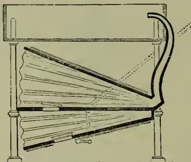
The great fault of the common bellows is, that it gives a succession of puffs, and not a continuous blast. One remedy for this was to use two bellows, so that one was blowing while the other was filling; but it was afterwards found that the double-bellows secured a still more uniform blast. This machine, shown in fig. 1, is merely the common bellows with a third board of the same shape as the other two placed between them, so as to form two chambers instead of one. The middle board is fixed, and both it and the lower one have valves placed in them opening inward. A weight on the lower board keeps the under chamber filled with air; and when this board is raised by a lever or otherwise, the air which it contains is forced into the upper chamber. The exit-pipe is attached to the latter, and a weight is placed on the upper board sufficiently heavy to press the air out in a continuous stream, the continuity being maintained by the large quantity of air always present in the upper chamber, and the uniform pressure of the weight. Even with the double-bellows, however, the blast is not quite regular.
Bellows made entirely of wood except the nozzle, first made in Germany in the 16th century, are in use in some continental countries, but they are only a modification of the common bellows.

The Chinese have a very simple form of bellows, shown in fig. 2, which is not only interesting in itself, but also because its action is almost the same as the blowing-engine. It is merely a square chamber of wood, with a close-fitting piston, which, when drawn from the nozzle, opens the valves, v, v, to admit air, and when pushed in the opposite direction, shuts these valves, and forces the air out by the nozzle.
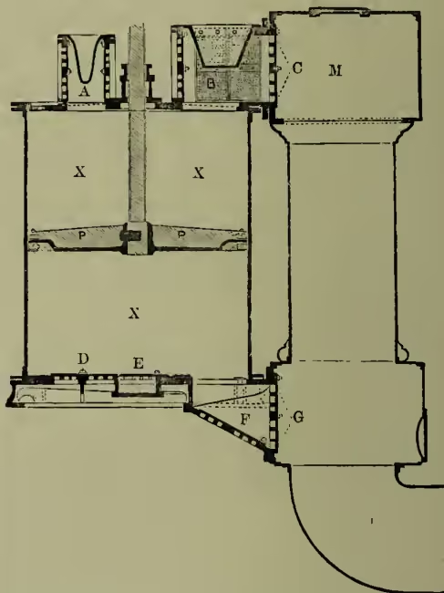
Blowing-engines.—For iron blast-furnaces and for Bessemer steel converters, blowing-engines of large size are employed. In the former, the strength of the blast is usually, in this country, from 3 to 4 lb. per square inch, sometimes it is 6 lb., and in the United States it is used at as high as 10 lb. For the Bessemer Converter (q.v.), where a much greater pressure is required, it occasionally reaches 30 lb. per square inch. A general view of a blowing-engine is given in the article IRON. It consists in its simplest form of a steam-cylinder, an air-cylinder, and a large air-chamber, to insure a uniform blast. Sometimes the latter is dispensed with, and large main-pipes used instead. We shall merely describe the blowing-cylinder here. It is marked X in fig. 3, and is of cast-iron, with an air-tight piston, P, which, as it ascends and descends with the motion of the engine, alternately inhales and expels the air at each end. To effect this, a series of valves are provided, and these are arranged as follows: Inlet valves are placed on the top of the cylinder at A, and also on three sides of the box at B, but on the fourth side of this box there are two outlet valves at C. These valves consist of numerous openings, against which leather flaps lie when they are shut. Valves of a similar nature are placed at the bottom of the cylinder; those for the inlet of air at D, E, and F; and those for outlet at G. When the piston descends, it would create a vacuum in the upper portion of the cylinder, provided there were no openings in it; but the external air pressing on the inlet valves, opens them, and fills the space above the piston; at the same time, the outlet valves at C, which only open outwards, are tightly closed by the air pressing inwards from the pipe, M. Again, when the piston ascends, it compresses the air above it, and exactly reverses the action of the valves; that is to say, it shuts the inlet valves at A and B, opens the valves at C, and allows the compressed air to pass along the outlet pipe, M, which is made of large size, so as to offer as little resistance as possible to the passage of the air. The valves at the bottom of the cylinder work exactly in the same way, the inlet valves, D, E, and F, opening when the piston ascends, and shutting when it descends, thus compelling the inhaled air to pass into the pipe, M, by the lower outlet valves at G. The air is conducted by the pipe, M, into a receiver of large capacity, which serves to equalise the blast before it passes to the tuyeres. See IRON, fig. 1.
A blast-engine at Shelton Ironworks, of which the blowing-cylinder is 8 feet 4 inches in diameter, and has a 9-feet stroke (represented in fig. 3), working with 186 horse-power, and making say 32 single strokes of the piston per minute, inhales 15,700 cubic feet of atmospheric air per minute; but this is compressed by the blowing-cylinder to a pressure of 3 lb. per square inch above the atmosphere, which reduces the volume supplied by the cylinder to 13,083 cubic feet. Its volume, however, is largely increased again, when raised to the hot-blast temperature, before entering the furnace. See Percy's Metallurgy, vol. ii.
Among the finest blowing-engines in England are those belonging to the Wigan Coal and Iron Co., and are situated at Kirkless Hall, near Wigan.
They were designed by the late Robert Wilson of the Bridgewater Foundry, near Manchester. Three pairs of engines are used, each pair consisting of a high and a low pressure steam-cylinder. The blowing-cylinders, six in number, are placed directly over the steam-cylinders, each of the former being 8 feet 4 inches in diameter with a stroke of 12 feet. One of these blowing-cylinders weighs 25 tons. Valve gear of ingenious construction admits of the engines being worked at different speeds to suit the number of blast-furnaces in operation.
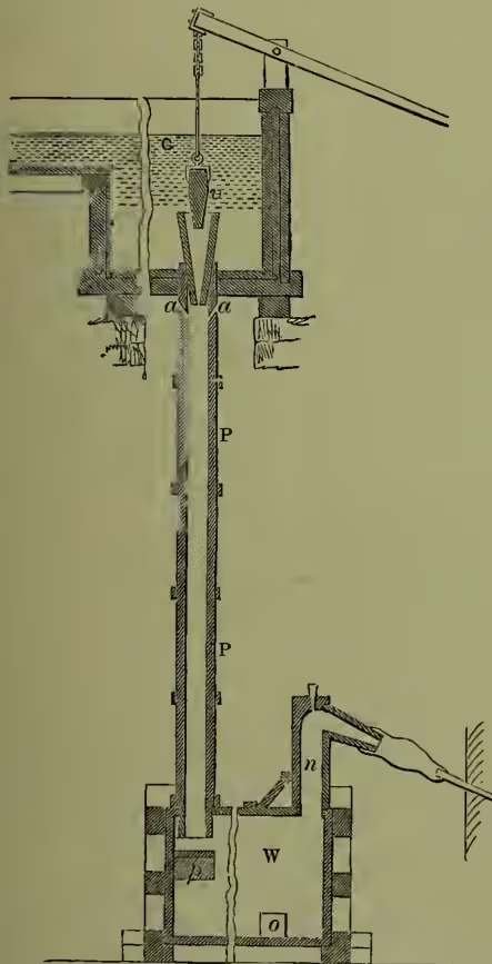
Trompe.—In the Catalan forges of Spain, the south of France, and some parts of America, there is a very ingenious water-blowing machine in use called a Trompe; but it can only be advantageously employed where a fall of a few yards of water is available. Its construction will be understood by an inspection of fig. 4. A strong wooden cistern, C, to act as a reservoir for the water; wooden pipes, P (generally two in number), through which it descends; and a wind-chest, W, to allow the air and water to separate, constitute the essential parts of the apparatus. It is put in operation by lifting the wedge v with a lever; this allows the water to rush down the pipe, and in doing so, draws in air through sloping holes, a, a, called aspirators, at the throat of the pipe. A continuous current of water and air is thus supplied to the wind-chest, which is provided with an opening at o for the escape of the water, while the air passes out in a regular stream by the nozzle-pipe at n. The height from which the water falls determines the tension of the blast; but the height seldom exceeds 27 feet, which gives a pressure of from to 2 lb. to the square inch. The separation of the air from the water is greatly promoted by the current impinging on the platform, p.
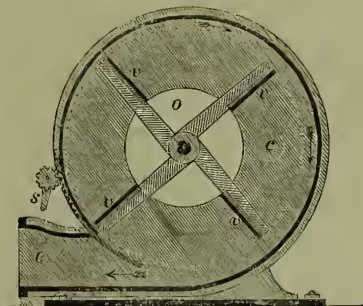
Fans.—The fan is another machine for producing blasts of air. It is employed for such purposes as the melting of pig-iron in foundries and for forge fires. It is also used as an exhaust to withdraw foul air from mines, public buildings, and ships. For mines it is occasionally of a very large size (see VENTILATION). The winnowing of corn is another application of it. The common blast-fan is shown in fig. 5. It is like a wheel with the arms tipped with vanes or blades, v, v, v, v, instead of being joined by a rim, and it is placed usually in an eccentric position, inside a chest, c, with central openings on each side for the admission of air, one of which is shown at o. It is generally driven by steam-power, and as it revolves, air is sucked in at the centre, drawn towards the tips, and impelled forward through the exit pipe, e.
Blast-fans seldom exceed 3 feet in diameter. The number of revolutions made per minute ranges from 700 to 1800; but the pressure of the fan-blast does not usually go beyond 6 ounces per square inch for ordinary foundry cupolas. Schiele's fan has numerous curved blades, and is nearly noiseless. It does not require much power to drive it, and has been very much used. Lloyd's fan has also curved blades, but they are fewer in number than in Schiele's. B. F. Sturtevant of Boston is the inventor of a fan with twelve curved blades, and with conical annular discs on the same axis. This form is very much liked in the United States (see the Engineer for 1883 and 1884).
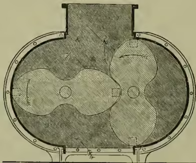
Rotary Pressure Blowers.—These are machines introduced in comparatively recent years. They act by regular displacement of the air at each revolution, since their pistons or drums closely fit their cases. In this respect they differ from fans, because, although there were no outlet for the blast, a fan could be kept revolving, but in such a case a pressure blower would stop. The rotary blower by Roots of Connersville, Indiana, is one of the best known, and is now very largely used for producing blasts in metallurgical operations, as well as for other purposes, in America and Europe. Its most improved form, patented in England in 1885, is shown in fig. 6. A pair of horizontal shafts traverse a case of the form of two semi-cylinders, separated by a rectangle equal in depth to the diameter of the semi-cylinders, and in width to the distance between the centres of the shafts. These shafts carry a pair of solid arms or pistons, the relative positions of which are maintained by external gearing at both ends provided with safety coverings. Each has a section somewhat resembling a figure of eight, and the action of which, as they revolve, takes the air in by an aperture at the bottom of the machine, and expels it with considerable pressure, if required, at the top. It gives a much greater pressure of blast than is attainable by the fan.
Another excellent machine of this kind, designed by J. G. Baker of Philadelphia, is employed for the same purposes as Roots's. It has a central drum with two vanes fairly fitting the two ends and the bored semi-cylindrical top of the case. Two lower drums, crescent-shaped in section, work by external gears at double the velocity of the central drum, the vanes of which move successively through the opening in each of the lower drums. The latter turn so as alternately to form abutments to prevent escape of air from either the entrance or delivery side. These rotary blowers produce blasts from a few ounces up to 3 lb. per square inch.