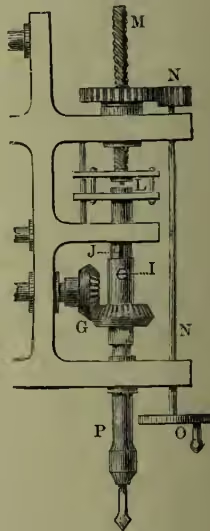
Boring is a process in mechanical and engineering operations, variously performed according to the medium dealt with. For making small holes in soft woods and like substances, awls are employed, which merely cut and displace a portion of the yielding material. In boring hard woods and large holes, carpenters use gimlets, augers, and the brace and bits, which all cut and scoop out the material. In the jewelry and small metal industries, hand-drills, which consist of a spindle with steel bits, to which reciprocating rotation is given, are the implements for piercing small holes. The boring of holes in metal plates is effected by means of drills driven by machinery. The annexed figure shows the essential parts of such a boring machine. The drill is inserted in the end of a vertical spindle, P, which revolves in a fixed frame, and is driven by the bevel-wheels, G. The metal to be bored is placed on a table or other support below the drill; and the up-and-down motion, or end-pressure and off-action, of the drill is effected by the hand-gear, O, N, turning the screw, M; which being coupled to the top of the spindle at L, presses it down or raises it, according to the way it is turned. The spindle slides vertically in the collar forming the axis of the bevel-wheel, but is carried round with it by means of the pin, I, which projects into a groove seen at J.
The boring of cannon and of cylinders for steam-engines, and for the propeller shafts of steamers, is most conveniently described under CANNON; see also LATHE.
As applied to the earth and to rocks, boring embraces two classes of operations—boring of shot-holes for Blasting (q.v.), and the sinking of bores in prospecting for minerals, and in forming wells for water, salt-brine, and mineral oils. Blast-holes in rocks are made from 1 to 2—sometimes more—inches in diameter, and may pierce to the depth of 9 feet. Such holes are most simply made in hard rock by a steel-pointed drill, struck by a hammer, and turned partly round after each blow to make the hole cylindrical. The addition of a little water serves to preserve the temper of the boring tool, and makes the rock more easy to cut. In soft rock, whenever the hole is to be vertical, a 'jumper' is used. This is a weighted drill, which acts merely by its own weight when let fall from about a foot in height. The powdered stone is removed at intervals by a 'scraper.' But in all great engineering undertakings rock-boring machinery now supplants hand work. The machines are principally devised to imitate the percussive action of the hand-drill, the boring chisel being worked and rotated by compressed air, and sometimes directly by steam. The compressed-air machines possess the great advantage of aiding in the ventilation of the working—often a most important consideration, seeing the operations are chiefly carried on in confined spaces where vast volumes of poisonous gases are evolved from explosions. The earliest practical rock-boring machine was that of Sommeiller, one of the engineers of Mont Cenis Tunnel, at which undertaking the apparatus was first used. Now the forms of percussion machines are very numerous, improvements being directed towards lightness and simplicity of parts, and to the method—automatic or otherwise—of advancing the boring tool as the work proceeds. Among the best-known machines classes of implement—(1) boring-rods, (2) rope-borers, and (3) diamond-drills.
The rod boring instrument consists of an iron shank, having a cross-bar at the top and a hollow screw at the bottom; to this all the successive boring instruments are fastened. A simple chisel is first attached to the screw, and one or two men press upon the cross-bar, and at the same time force it round like an auger; while another workman, by means of a lever erected overhead, with a chain descending from it to the cross-bar, gives an up-and-down motion to the instrument. When the chisel becomes clogged, from the accumulation of material which it has loosened, it is exchanged for a cylindrical auger, provided with a valve, which scoops out the separated material; and thus by alternate chopping and scooping the work is carried on. The nature of the strata is determined with considerable facility and certainty by examining the fragments brought up by the auger. As the work advances, successive lengths of rod are screwed on at the upper end. A derrick pole is erected over the bore-hole for the purpose of elevating the rods, to permit the change of the tools.
The rope method of boring has been long in use among the Chinese. By it the great loss of time, arising from the screwing and unscrewing the rods, at each elevation of the chisel or auger, is saved. The chisel and scooping instrument are fastened to a rope, which is alternately elevated and allowed to descend by the simple force of gravity; the instrument thus forces its way through the ground. In the softer rocks of the newer formations this method has been successfully employed in boring for artesian wells. The rope-boring machinery of Mather and Platt of Salford, in which a flat hempen rope is employed, is in extensive use.
For deep well-sinking, as in the Pennsylvanian oil region where depths of 2000 feet and more have to be reached, and for mineral prospecting, the diamond-drill has of late years largely superseded all other borers. With this apparatus the earth can be pierced at any angle, which is a great advantage in investigating mineral deposits; and moreover, the drill produces solid and continuous cores of the strata through which it passes, so that a complete section of any bore can be exposed to view. The diamond-drill consists of a 'crown,' or cylinder of steel, around one edge of which are fixed a series of black diamonds. These diamonds are so set that they project alternately a little beyond the outside and inside edge of the cylinder. This crown is screwed to lengths of iron tubing as it cuts its way by rotation into the rock, and it makes as it descends an annular cutting somewhat bigger than the thickness of the continuous tube, which the crown and its shaft form. Thus a core of rock is cut out and held within the tube, and the pieces may be lifted out from time to time as the work proceeds. The detritus resulting from the abrasion of the ring of rock is continuously washed away by a current of water forced down within the tubing. Diamond-drills are made of many sizes, from up to 18 inches diameter. The prototype of the diamond-drill was M. Fauvelle's hollow boring-rod with steel crown described at the British Association meeting in 1846.